MR-signal emitting coatings

a technology of mrsignal and coating, which is applied in the direction of nmr/mri constrast preparation, measurement using magnetic resonance, packaging goods type, etc., can solve the problems of difficult to determine position at more than a few discrete points along the device, and large dose of ionizing radiation exposure, etc., to achieve high signal, easy visualization, and easy visualization

Inactive Publication Date: 2005-05-24
WISCONSIN ALUMNI RES FOUND
View PDF26 Cites 25 Cited by
  • Summary
  • Abstract
  • Description
  • Claims
  • Application Information

AI Technical Summary

Benefits of technology

[0016]The present invention provides a process for coating medical devices so that the devices are readily visualized, particularly, in T1 weighted magnetic resonance images. Because of the high signal caused by the coating, the entirety of the coated devices can be readily visualized during, e.g., an endovascular procedure.
[0023]In yet another aspect, the invention provides a method of reducing the mobility of paramagnetic metal ion / chelate complexes covalently linked to a solid polymer substrate of a medical device. This method includes providing a medical device having paramagnetic metal ion / chelate complexes covalently linked to the solid polymer substrate of the medical device. The method also includes encapsulating at least a portion of the medical device having at least one of the paramagnetic metal ion / chelate complexes covalently linked thereto with a hydrogel. The hydrogel reduces the mobility of at least one of the paramagnetic metal ion / chelate complexes, and thereby enhances the magnetic resonance imageability of the medical device.

Problems solved by technology

Safety issues are associated with the relatively large dosages of ionizing radiation required for x-ray fluoroscopy and angiographic guidance.
While radiation risk to the patient is of somewhat less concern (since it is more than offset by the potential benefit of the procedure), exposure to the interventional staff can be a major problem.
It is likely that once suitable MR-based endovascular procedures have been developed, the next challenge will be to integrate this functional information with conventional anatomical imaging and device tracking.
Although it is possible to incorporate multiple RF coils (4-6 on typical clinical MR systems) into a device, it is still impossible to determine position at more than a few discrete points along the device.
While this may be acceptable for tracking rigid biopsy needles, this is a significant limitation for tracking flexible devices such as those used in endovascular therapy.
The attachment of coils onto flexible catheters presents numerous challenges in maintaining the functionality of the catheter as these coils result in changes in the mechanical properties of the catheter onto which they are incorporated.
This allows visualization of a considerable length of a catheter, but still does not address the problems of RF heating and the mechanical changes which degrade catheter performance.
This results in such a device being seen as an area of signal loss or signal void in the MR images.
Since air, cortical bone and flowing blood are also seen in MR images as areas of signal voids, the use of signal void is generally not appropriate for tracking devices used in interventional MR.
One problem with the use of these techniques based on susceptibility artifacts is the fact that those used for localization of the device does not correspond precisely with the size of the device.
This makes precise localization difficult.
A principal drawback of these passive techniques is that visualization is dependent on the orientation of the device with respect to the main magnetic field.
Despite recognition and study of various aspects of the problems of visualization of medical devices in therapeutic, especially endovascular, procedures, the prior art has still not produced satisfactory and reliable techniques for visualization and tracking of the entire device in a procedure under MR guidance.

Method used


Image

  • MR-signal emitting coatings
  • MR-signal emitting coatings
  • MR-signal emitting coatings

Examples


example 1

Preparation of Coated Polyethylene Sheets

[0095]Polyethylene sheets were coated in the three-step process described herein.

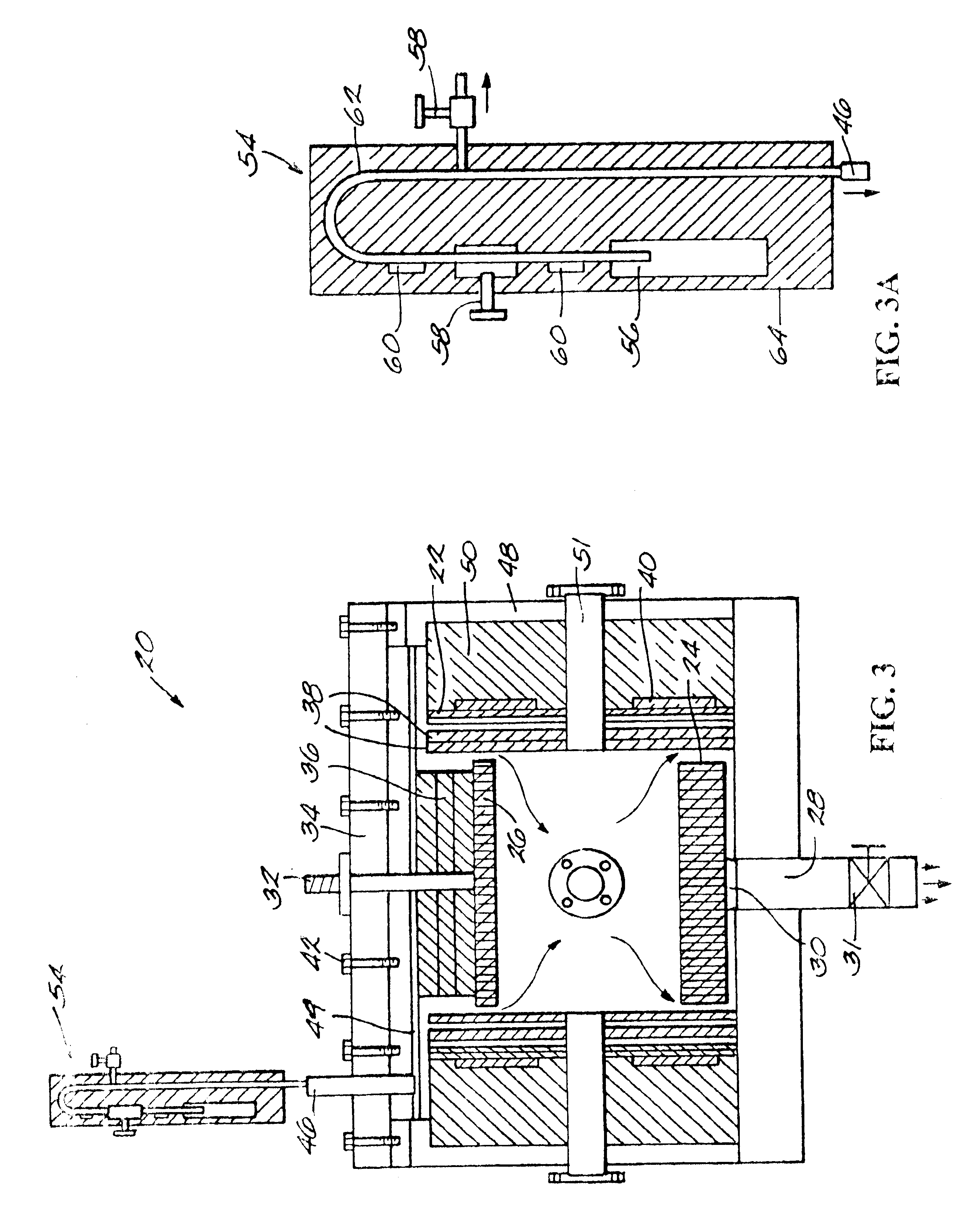
[0096]Surface Amination. A polyethylene sheet (4.5 in diameter and 1 mil thick) was placed in a capacitively coupled, 50 kHz, stainless steel plasma reactor (as shown schematically in FIGS. 3 and 3A) and hydrazine plasma treatment of the polyethylene film was performed. The substrate film was placed on the lower electrode. First, the base pressure was established in the reactor. Then, the hydrazine pressure was slowly raised by opening the valve to the liquid hydrazine reservoir. The following plasma conditions were used: base pressure=60 mT; treatment hydrazine pressure=350 mT; RF Power=25 W; treatment time=5 min; source temperature (hydrazine reservoir)=60° C.; temperature of substrate=40° C. Surface atomic composition of untreated and plasma-treated surfaces were evaluated using XPS (Perkin-Elmer Phi-5400; 300 W power; Mg source; 15 kV; 45° takeoff angle).

[009...

example 2

Preparation of Coated Polyethylene sheets Including Linker Agent

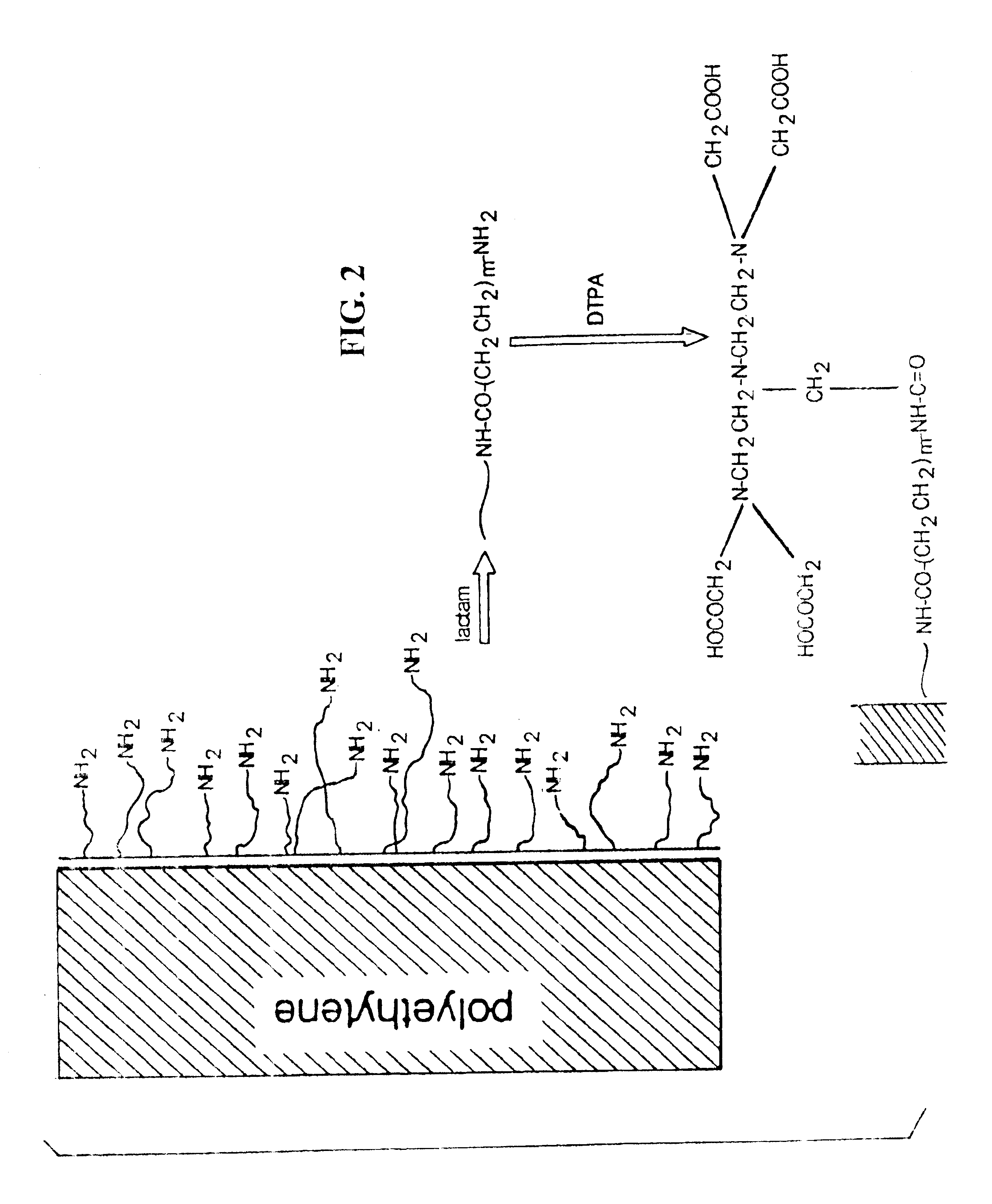
[0101]Coated polyethylene sheets were prepared according to the method of Example 1, except that after surface amination, the polyethylene sheet was reacted with a lactam, and the sheet washed before proceeding to the chelation step. The surface of the film was checked for amine groups using XPS.

example 3

Imaging of Coated Polyethylene and Polypropylene Sheets

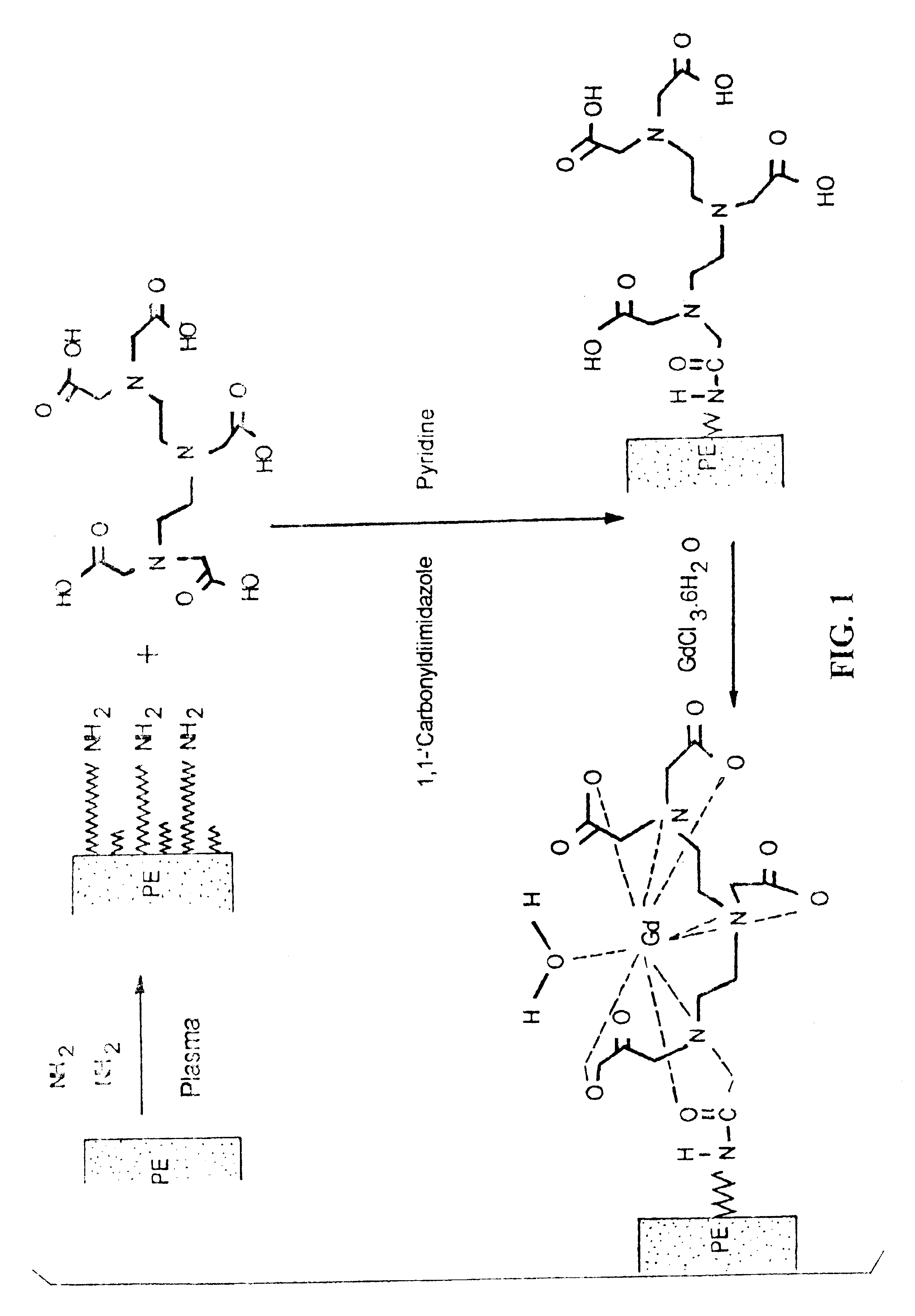
[0102]MR signal enhancement was assessed by imaging coated sheets of polyethylene and polypropylene, prepared as described in Example 1, with gradient-recalled echo (GRE) and spin-echo (SE) techniques on a clinical 1.5 T scanner. The sheets were held stationary in a beaker filled with a tissue-mimic, fat-free food-grade yogurt, and the contrast-enhancement of the coating was calculated by normalizing the signal near the sheet by the yogurt signal. The T1-weighed GRE and SE MR images showed signal enhancement near the coated polymer sheet. The T1 estimates near the coated surface and in the yogurt were 0.4 s and 1.1 s, respectively. No enhancement was observed near control sheets. The MR images acquired are shown in FIG. 4.


PUM

PropertyMeasurementUnit
thicknessaaaaaaaaaa
diameteraaaaaaaaaa
diameteraaaaaaaaaa

Abstract

The present invention provides a coating that emits magnetic resonance signals and a method for coating medical devices therewith. The coating includes a paramagnetic metal ion-containing polymer complex that facilitates diagnostic and therapeutic techniques by readily visualizing medical devices coated with the complex. The present invention also provides methods by which pre-existing polymers and medical devices may be made MR-imageable. The invention also provides methods of improving MR-imageability of polymers and medical devices by encapsulating the polymers and medical devices with hydrogels.

Description

CROSS-REFERENCE TO RELATED APPLICATIONS[0001]This application is a continuation-in-part of and claims priority to U.S. application Ser. No. 10 / 096,368 filed on Mar. 12, 2002 which is a continuation of and claims priority to U.S. application Ser. No. 09 / 105,033 which was filed on Jun. 25, 1998 and issued as U.S. Pat. No. 6,361,759 on Mar. 26, 2002 and claims the benefit of the priority date under 35 U.S.C. §119 of U.S. Provisional Application No. 60 / 086,817, filed May 26, 1998. This application claims priority to each of these applications and hereby fully incorporates the subject matter of each of these applications.STATEMENT REGARDING FEDERALLY SPONSORED RESEARCH OR DEVELOPMENT[0002]This invention was made with Government support under Grant Nos. NIH 1 ROI HL57983; NIH 1 R29 HL57501 awarded by the National Institutes of Health, and NSF-DMR 9711226, 0084301 and NSF-EEC 8721845(ERC) awarded by the National Science Foundation. The U.S. Government has certain rights in this invention.B...

Claims


Application Information

Patent Timeline
Patent Type & Authority Patents(United States)
IPC IPC(8): A61K49/18A61L29/00A61K49/06A61K49/08A61L31/14A61L29/18A61L31/18G01R33/28A61B5/055A61L31/00A61M25/00
CPCA61K49/085A61K49/128A61K49/1803G01R33/285A61L29/18A61L31/10A61L31/18A61L29/085
Inventor LI, JUNWEIUNAL, ORHANJIANG, XIQUNSTROTHER, CHARLES MILTONYU, HYUK
Owner WISCONSIN ALUMNI RES FOUND
Why Eureka
Try Eureka