Differential dual floating gate circuit and method for programming

a technology of differential circuit and floating gate, applied in the field of differential circuit and differential circuit for accurate voltage reference, can solve the problems of net negative charge on floating gate fg, less efficient and desirable dual conduction digital programming of floating gate, and limited circuit b>70/b> accuracy, etc., to achieve improved initial setting accuracy, less power consumption, and improved accuracy over bandgap voltage reference

Inactive Publication Date: 2005-05-24
XICOR
View PDF13 Cites 30 Cited by
  • Summary
  • Abstract
  • Description
  • Claims
  • Application Information

AI Technical Summary

Benefits of technology

[0019]A key advantage of the present invention is the improved initial setting accuracy over prior art floating gate voltage references by more than a factor of 100.
[0020]Another key advantage of the present invention is that, without the need for using laser trimming or E2 digital trimming, the present invention has an improved accuracy over bandgap voltage references of a factor of 10 to 50 while drawing less power by a factor of more than 10. Moreover, a voltage reference of greater than or less than 1.2 volts can be set using the present invention without the need for additional amplifiers.
[0021]Another advantage of the present invention is that, after a high voltage set mode, the invention allows for a controlled ramp down sequence to ramp down the voltages at each floating gate erase and program electrode such that, when voltage and current sources are completely shut down in the circuit, a more accurate voltage is set on the floating gates.
[0022]Another advantage of the present invention is that the voltage at the erase electrode that is coupled to the reference floating gate is controlled during the ramp down sequence by shutting off the negative voltage charge pump while allowing the feedback circuit to remain active.
[0023]Another advantage of the present invention is that tunnel current is used to self-discharge the voltage at each program electrode.
[0024]Another advantage of the present invention is that any voltage and current offsets coupled through the tunnel devices to the corresponding floating gates and any offsets in the transistors used in the floating gate circuit are common mode because of the use of dual floating gates, and do not change the voltage differential produced by the floating gates, and thus do not change the programmed voltage reference at the output during a read mode.

Problems solved by technology

This results in a net negative charge on floating gate fg.
Second, the accuracy of circuit 70 is also limited because the potential of floating gate fg changes another 100 mV to 200 mV over time after it is set due to various factors, including detrapping of the tunnel devices and dielectric relaxation of all the floating gate fg capacitors.
However, this method has only been used in digital circuits to program the floating gate to either a “1” condition or a “0” condition to provide memory storage.
The precise charge on the floating gate in such applications is not of concern and so is not precisely controlled in such circuits.
According to the prior art, such dual conduction digital programming of a floating gate is considered to be a less efficient and desirable way than generating electron conduction through a single tunnel element to control the level of charge on a floating gate.
Known disadvantages of dual conduction digital programming of a floating gate include the fact that a larger total voltage is required to provide dual conduction and tunnel oxide trap-up is faster because more tunnel current is required.
In this device, however, only one Fowler-Nordheim tunnel device is used.
A key problem with such prior art devices is that they do not compensate for common-mode voltage and current offsets, common-mode temperature effects, and mechanical and thermal stress effects in the integrated circuit.

Method used


Image

  • Differential dual floating gate circuit and method for programming
  • Differential dual floating gate circuit and method for programming
  • Differential dual floating gate circuit and method for programming

Examples


Embodiment Construction

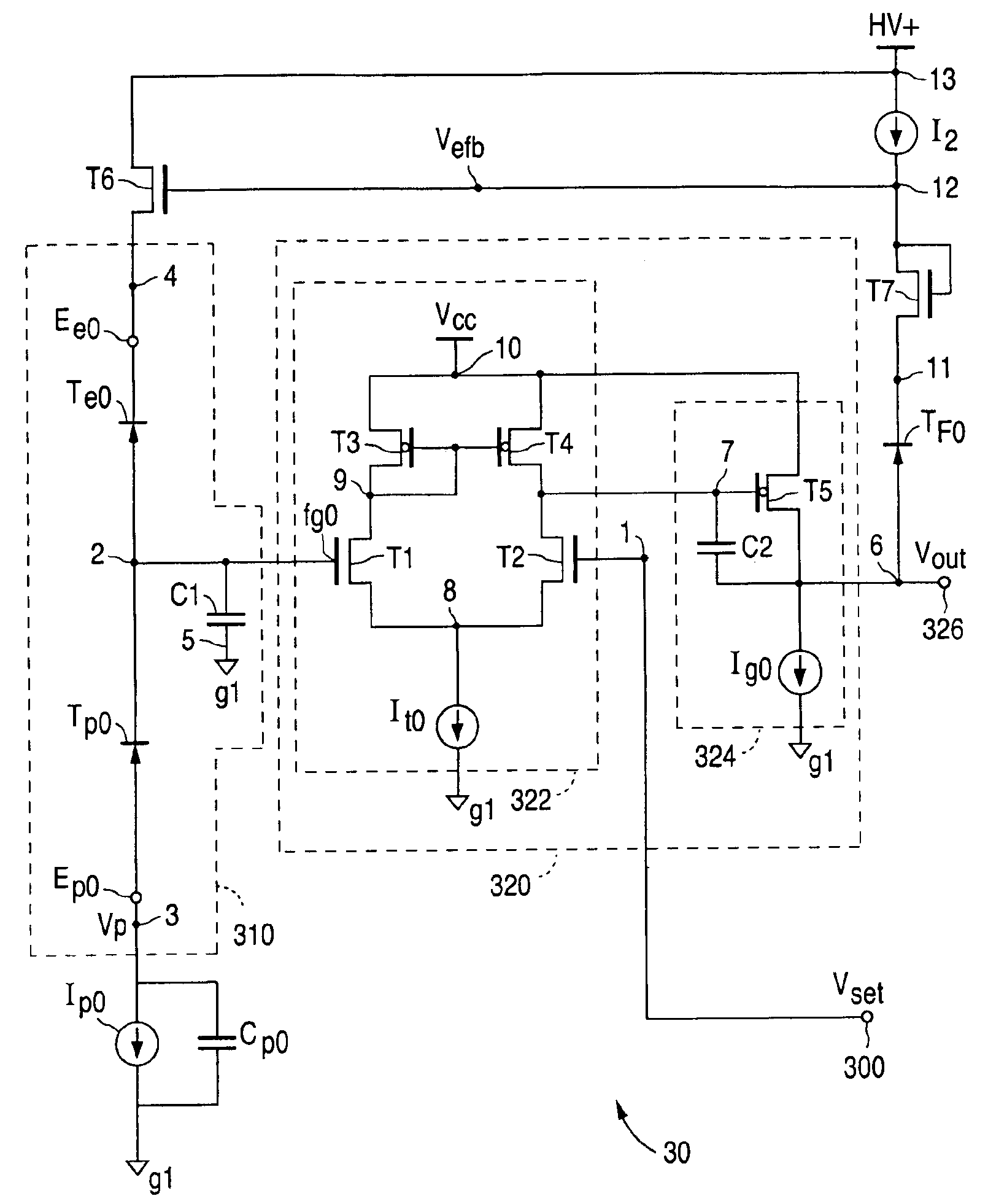
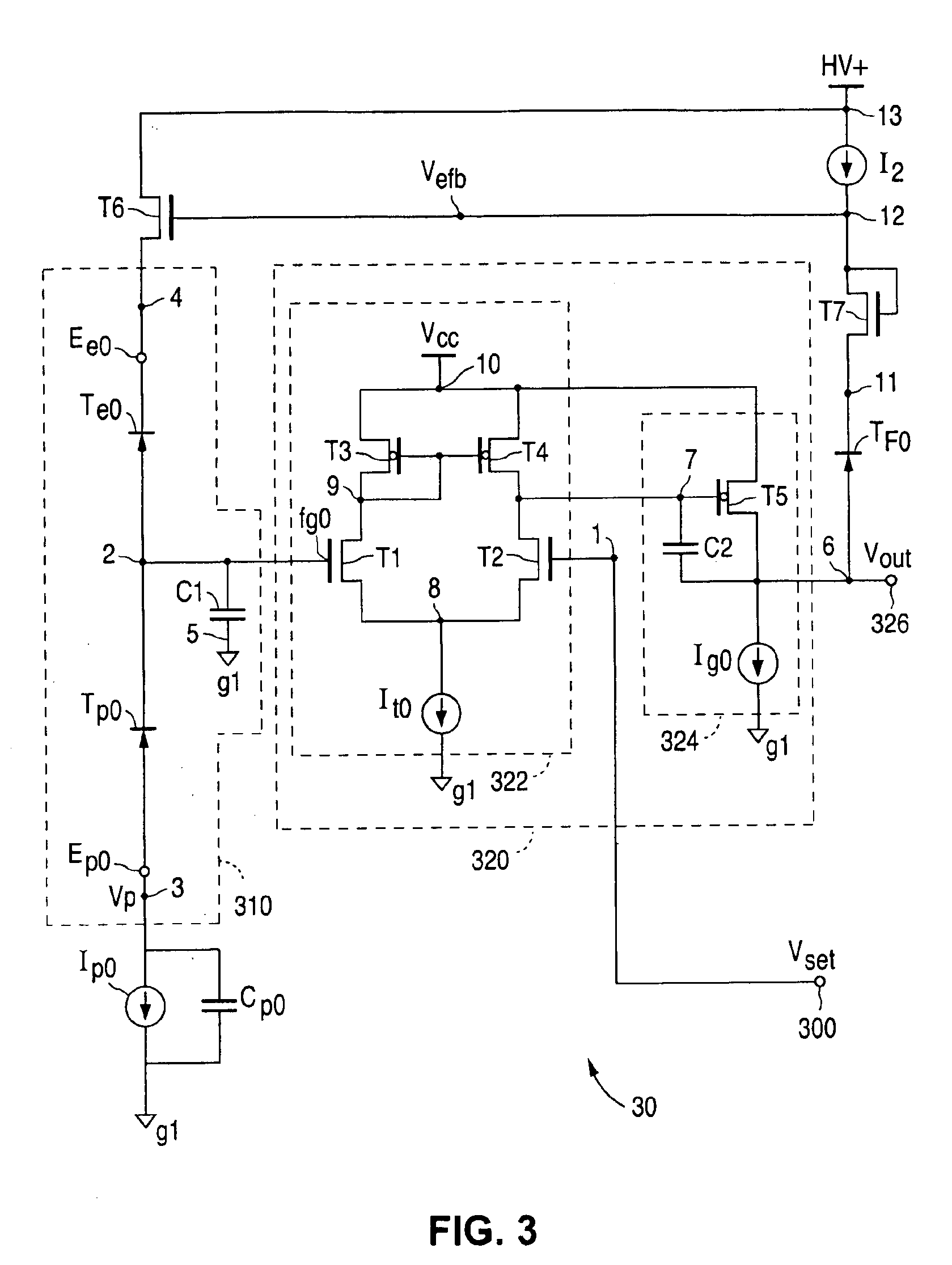
[0043]FIG. 3 is a circuit diagram of a differential single floating gate circuit 30 according to the present invention for accurately setting a floating gate to an analog voltage during a high voltage set mode or set cycle. FIG. 4A is a circuit diagram of a differential dual floating gate circuit 40 according to another embodiment of the present invention. Circuit 40 is also used to accurately set a floating gate to an analog voltage during a high voltage set mode. Once the analog voltage level is set, both circuit 30 and circuit 40 can then be configured during a read mode as a precise voltage comparator circuit with a built-in voltage reference or a precise voltage reference circuit. Circuit 30 and circuit 40 are preferably implemented as an integrated circuit manufactured using industry standard CMOS processing techniques. Since the sequence used during the set mode is similar for both circuits, circuit 30 and the method for programming a floating gate using circuit 30 will be de...


PUM


Abstract

A method and circuit for setting a reference voltage in a dual floating gate circuit is disclosed. During a set mode, a first and second floating gate are programmed to different charge levels that are a function of an input set voltage capacitively coupled to the first floating gate during the set mode. During a read mode, this difference in charge level is used by the dual floating gate circuit to generate a reference voltage that is a function of the input set voltage, and is preferably equal to the input set voltage.

Description

FIELD OF THE INVENTION[0001]This invention relates to a method and circuit for an accurate voltage reference, and more specifically to a differential circuit that uses a feedback loop and dual conduction of tunnel devices to accurately program a desired charge level on a floating gate.BACKGROUND OF THE INVENTION[0002]Programmable analog floating gate circuits have been used since the early 1980's in applications that only require moderate absolute voltage accuracy over time, e.g., an absolute voltage accuracy of 100-200 mV over time. Such devices are conventionally used to provide long-term non-volatile storage of charge on a floating gate. A floating gate is an island of conductive material that is electrically isolated from a substrate but capacitively coupled to the substrate or to other conductive layers. Typically, a floating gate forms the gate of an MOS transistor that is used to read the level of charge on the floating gate without causing any leakage of charge therefrom.[00...

Claims


Application Information

Patent Timeline
Patent Type & Authority Patents(United States)
IPC IPC(8): G11C27/00
CPCG11C27/005
Inventor OWEN, WILLIAM H.
Owner XICOR
Why Eureka
Try Eureka