Imaging system and methodology employing reciprocal space optical design

a technology of optical design and optical design, applied in the field of image and optical systems, to achieve the effect of facilitating the imaging performance of optical imaging systems, and reducing the number of optical components

Inactive Publication Date: 2005-06-07
PIXEL MATCHED HLDG
View PDF2 Cites 27 Cited by
  • Summary
  • Abstract
  • Description
  • Claims
  • Application Information

AI Technical Summary

Benefits of technology

[0019]The present invention relates to a system and methodology that facilitates imaging performance of optical imaging systems. In regard to several optical and / or imaging system parameters, many orders of performance enhancement can be realized over conventional systems (e.g., greater effective magnification, larger working distances, increased absolute spatial resolution, increased spatial field of view, increased depth of field, Modulation Transfer Function of about 1, oil immersion objectives and eye pieces not required). This is achieved by adapting an image transfer medium (e.g., one or more lenses, fiber optical media) to a sensor having one or more receptors (e.g., pixels) such that the receptors of the sensor are effectively scaled (e.g., “mapped”, “sized”, “projected”, “matched”, “reduced”) to occupy an object field of view at about the scale or size associated with a diffraction limited point or spot within the object field of view. Thus, a band-pass filtering of spatial frequencies in what is known as Fourier space or “k-space” is achieved such that the projected size (projection in a direction from the sensor toward object space) of the receptor is filled in k-space.
[0021]According to one aspect of the present invention, a “k-space” design, system and methodology is provided which defines a “unit-mapping” of the Modulation Transfer Function (MTF) of an object plane to image plane relationship. The k-space design projects image plane pixels or receptors forward to the object plane to promote an optimum theoretical relationship. This is defined by a substantially one-to-one correspondence between image sensor receptors and projected object plane units (e.g., units defined by smallest resolvable points or spots in the object field of view) that are matched according to the receptor size. The k-Space design defines that “unit-mapping” or “unit-matching” acts as an effective “Intrinsic Spatial Filter” which implies that spectral components of both an object and an image in k-space (also referred to as “reciprocal-space”) are substantially matched or quantized. Advantages provided by the k-space design result in a system and methodology capable of much higher Effective Magnification with much increased Field Of View, Depth Of Field, Absolute Spatial Resolution, and Working Distances utilizing dry objective lens imaging, for example, and without employing conventional oil immersion techniques.

Problems solved by technology

The resolution demonstrated by lenses operating at the limits of diffraction theory, however, is rarely achieved in practice without sacrificing other desirable characteristics.
Unfortunately, increased magnification in conventional microscope designs generally causes tradeoffs in other design features such as resolution and contrast.
Conventional microscope designs limit useful magnifications to approximately 1000 times (×) since the intrinsic spatial resolution of the lenses cannot exceed limits dictated by the well-known Rayleigh equation:
Any increase in magnification increases image size but also results in well-known increased detail blur at the image plane.
Though many of the imaging applications mentioned above, employ these techniques regularly, the methods have been subject to optical and illumination related limitations that can cause substantial degradation of image quality and usefulness when high magnification and resolution are required.
Well-defined and known limitations of conventional high-magnification and / or high-resolution imaging systems include but are not limited to:(1) Very narrow Field Of View (FOV) and very small Working Distance (WD) for high effective magnification;(2) High Effective Magnification limited to “useful magnification” at accepted maximum of about 1000× and is determined by well-known optical diffraction effects which govern absolute possible spatial resolution in optical images;(3) Very small Depth Of Field (DOF) typically less than 1 micron at high magnification; Inhomogeneous illumination sources (varying intensity across even a small field) are extremely position sensitive for correct magnification and contrast vs. spatial resolution for non-quantifiable “pleasing appearance” versus well known “empty resolution” in clinical and industrial microscopy;(4) Objective lens to object distance decreases in operation from low to high power objective lenses in order to increase effective magnification (typical 15 to 20 mm for low power objective to fraction of a millimeter for up to 50× objectives;(5) Highest Numerical Aperture is required for high magnification and is generally only achievable with immersion-type objective lenses; and(6) Very high Effective Magnification generally requires 50× to 100× objective lenses typical for object image projection to magnifying eyepiece or subsequent imaging device and have inherently short working distance and very small Field Of View as well as other limitations, including “empty magnification” problems.< / ul
Other problems with conventional imaging systems relate to oil immersion objective lenses to increase the numerical aperture through Index of Refraction matching fluid such as oil for objective magnification over 50× are typically (e.g., at 100×) required to achieve effective through-the-eyepiece magnifications of up to 1000×.
Other issues involve the small “circle of least confusion” (object plane image diameter) magnified by an inspection lens system (generally an optical eyepiece or equivalent) for projection onto an image sensor limiting spatial resolution to a number of sensor pixels across a projected image on to the sensor.
This inherently limits both a Modulation Transfer Function that defines contrast versus resolution and absolute spatial resolution.
Still other problems can involve conventional “Infinity-corrected” microscope objectives that are designed with optical parameter correction for an effective “infinite-tube-length”, thus these lenses can require a telescope objective lens (also called the “tube-lens”) in addition to an eyepiece to bring the image into focus for the eye.
This is an accepted method of optical design employing geometrical optics design rules and results in even the most advanced conventional microscopic imaging systems having the aforementioned well-known limitations in projected Field Of View, Effective Magnification, Absolute Spatial Resolution, and Diffraction Limitations at the imaging device.
However, even the most advanced systems generally limit to two the number of such additional added components without specifying additional correcting optics.
Another problem with conventional high magnification image designs relates to special configurations to employ either transmissive or reflected illumination techniques.
These designs are also labor intensive for operational adjustment and for optimum image quality from sample to sample under examination.
As can be appreciated, modern optical designs employing high-grade oil immersion lenses and / or other correcting optics generally involves significant expense.

Method used


Image

  • Imaging system and methodology employing reciprocal space optical design
  • Imaging system and methodology employing reciprocal space optical design
  • Imaging system and methodology employing reciprocal space optical design

Examples


Embodiment Construction

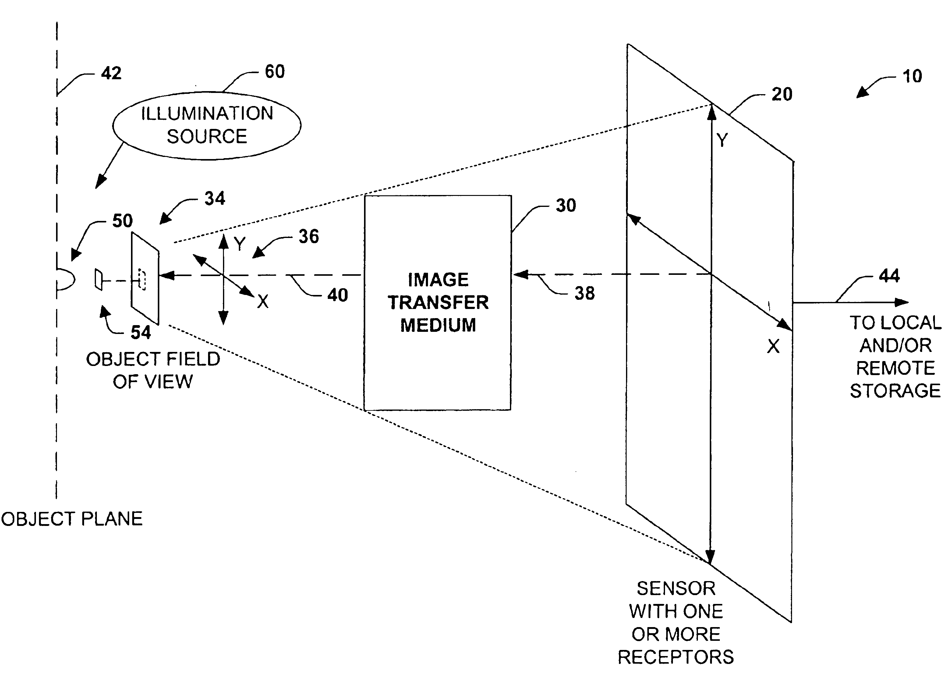
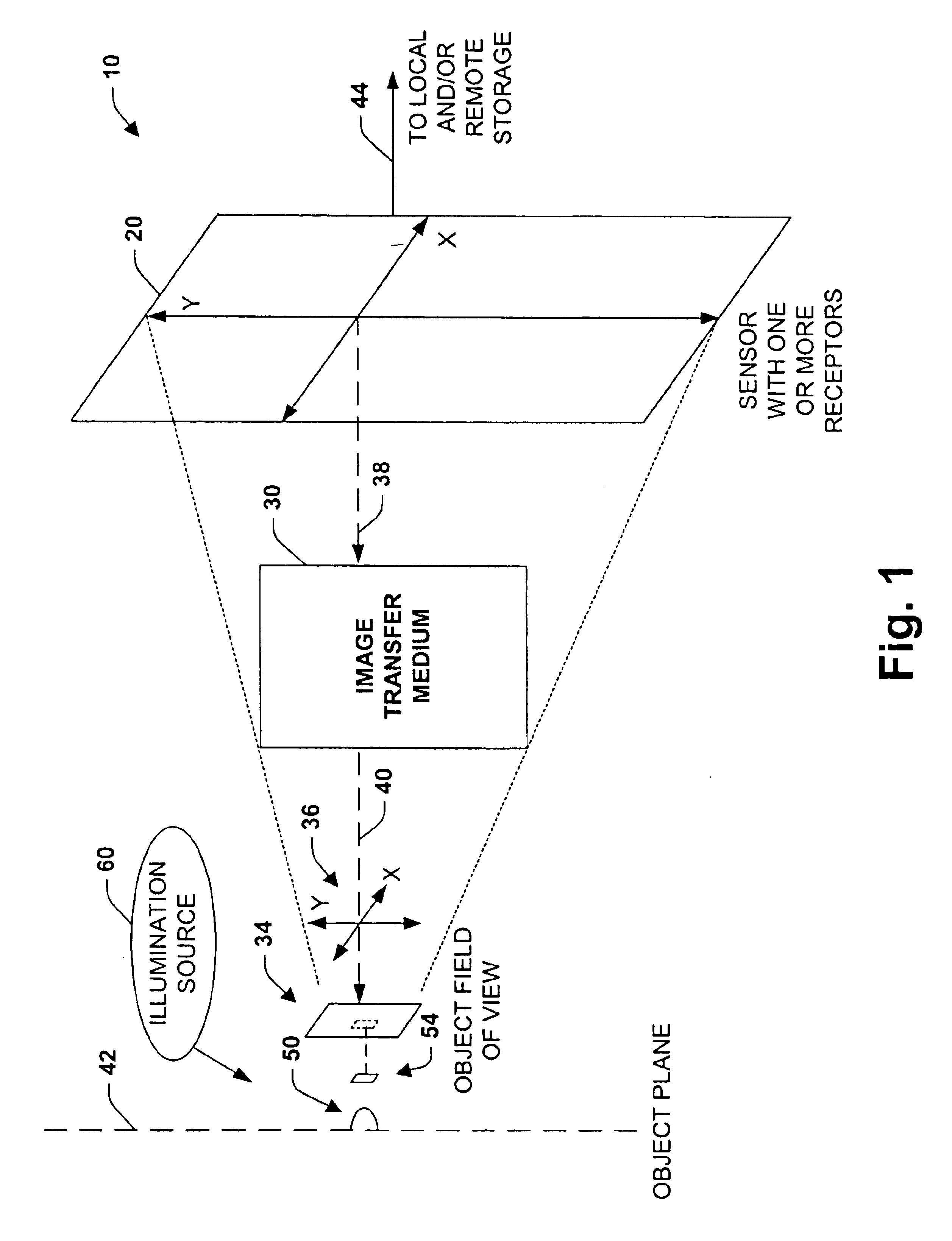
[0032]The present invention relates to a system and methodology that greatly enhances a plurality of characteristics and / or parameters associated with microscopy and imaging in general. This enables technology for a plurality of applications utilizing a novel design approach which can include a general modular base-system to provide high effective magnification and high spatial resolution among other features. As an example, this can include vision-based microscopic imaging for a variety of applications while mitigating well-known disadvantages of conventional imaging designs and practices. Applications for the present invention can employ image and optical measurement of various samples, objects, materials, and / or matter and also provide for various microscopic imaging and measurement situations such as material, sample handling, inspection and analysis, for example.

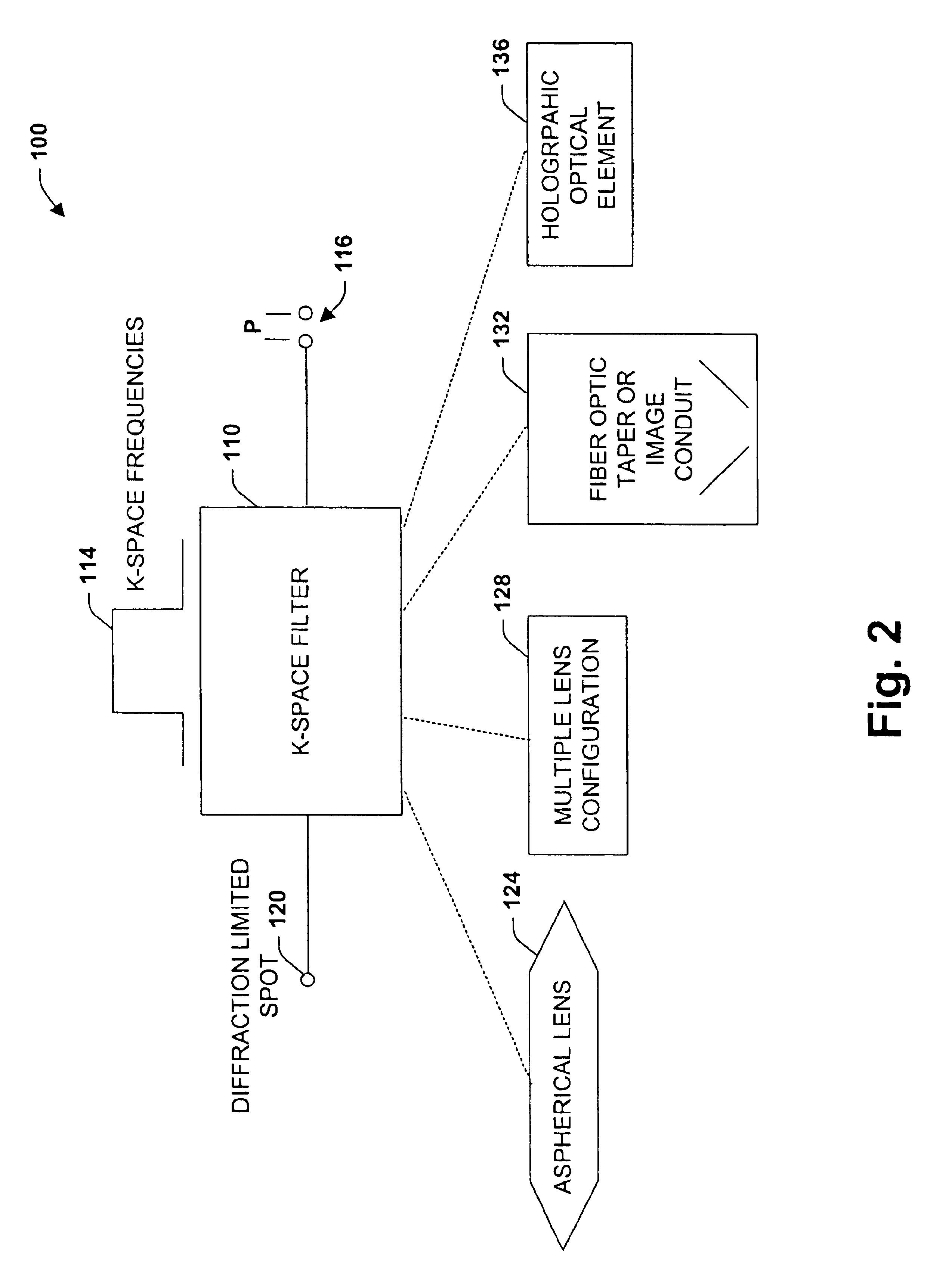
[0033]According to one aspect of the present invention, a k-space filter is provided that can be configured from an i...


PUM


Abstract

An imaging system and methodology is provided to facilitate optical imaging performance. The system includes a sensor having one or more receptors and an image transfer medium to scale the sensor and receptors to an object field of view. A computer, memory, and / or display associated with the sensor provides storage and / or display of information relating to output from the receptors to produce and / or process an image, wherein a plurality of illumination sources can also be utilized in conjunction with the image transfer medium. The image transfer medium can be configured as a k-space filter that correlates a pitch associated with the receptors to a diffraction-limited spot within the object field of view, wherein the pitch can be unit-mapped to about the size of the diffraction-limited spot within the object field of view.

Description

PRIORITY CLAIM[0001]This application is a continuation application of Ser. No. 10 / 403,744, filed on Mar. 31, 2003, and entitled IMAGING SYSTEM AND METHODOLOGY EMPLOYING RECIPROCAL SPACE OPTICAL DESIGN, which is a continuation application of U.S. Ser. No. 09 / 900,218, filed on Jul. 6, 2001, and entitled IMAGING SYSTEM AND METHODOLOGY EMPLOYING RECIPROCAL SPACE OPTICAL DESIGN, and now issued as U.S. Pat. No. 6,664,528. These related applications are incorporated herein by reference.TECHNICAL FIELD[0002]The present invention relates generally to image and optical systems, and more particularly to a system and method to facilitate imaging performance via an image transfer medium that projects characteristics of a sensor to an object field of view.BACKGROUND OF THE INVENTION[0003]Optical technologies and sciences related to such fields as microscopy have evolved from ancient observations and understandings of the nature of light to the manner in which light can be manipulated via one or m...

Claims


Application Information

Patent Timeline
Patent Type & Authority Patents(United States)
IPC IPC(8): H01L27/00G02B27/46
CPCG02B27/46
Inventor CARTLIDGE, ANDREW G.FEIN, HOWARD
Owner PIXEL MATCHED HLDG
Why Eureka
Try Eureka