Ion detector

a detector and microchannel plate technology, applied in the field of detectors, can solve the problems of inaccurate isotopic ratio determination, limited dynamic range of microchannel plate ion detectors, inaccurate mass measurement, etc., and achieve the effect of narrowing the pulse height distribution and minimizing the broadening of the pulse height distribution

Active Publication Date: 2005-06-14
MICROMASS UK LTD
View PDF12 Cites 23 Cited by
  • Summary
  • Abstract
  • Description
  • Claims
  • Application Information

AI Technical Summary

Benefits of technology

[0121]In another embodiment the secondary electrons released from the first microchannel plate are focused or guided onto a discrete area of the detecting surface of the detecting device at any one particular time. The detecting device may comprise one or more microchannel plates having a larger total area than the first microchannel plate. In this embodiment the secondary electrons are preferably focused so that the secondary electrons are preferably incident on the minimum number of channels possible in the one or more microchannel plates of the detecting device. The secondary electrons released from the first microchannel plate may preferably be continuously swept, guided or rotated or periodically switched, guided or rotated between different areas of the second microchannel plate arrangement by a time-varying electric and/or magnetic deflection field. The average number of secondary electrons received by any one area of the one or more microchannel plates of the detecting dev

Problems solved by technology

However, under optimal operating conditions the dynamic range of microchannel plate ion detectors can be limited.
This has the result of causing there to be a non-linearity in the response of the ion detector for quantitative analysis which will result in inaccurate isotopic ratio determinations and inaccurate mass measurements.
However, reducing the gain would cause broadening of the pulse height distribution and would shift the pulse height distribution to a lower intensity resulting in a compromise in the ability of the ion detector to detect all single ion arrivals above the threshold of electronic noise.
However, there are also practical limitations.
The negative temperature coefficient of resistance of the channel walls in the microchannel plate ultimately results in thermal instability as the resistance of the microchannel plate is reduced.
This causes heating of the microchannel plate which can result in ion feedback leading to thermal runaway which may result in local melting of the

Method used


Image

  • Ion detector
  • Ion detector
  • Ion detector

Examples


Embodiment Construction

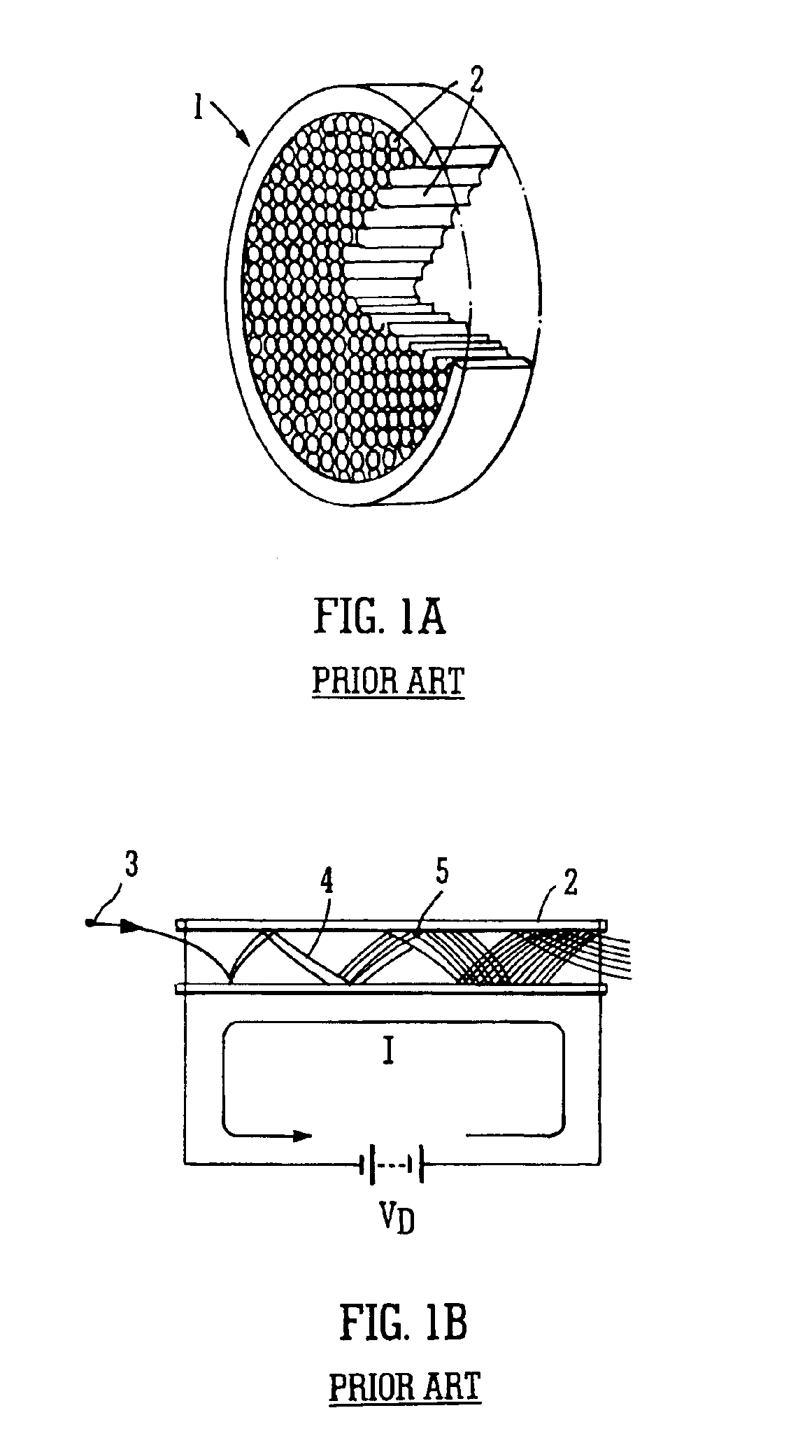
[0138]A conventional microchannel plate is shown in FIG. 1A. The microchannel plate 1 comprises a periodic array of very small diameter glass capillaries or channels 2 which have been fused together and sliced into a thin plate. Microchannel plates 1 typically have several million channels 2 and each channel 2 functions as an independent electron multiplier.

[0139]FIG. 1B shows the operation of a single channel 2 of a microchannel plate 1. A single incident particle 3, e.g. an ion (or less preferably an electron or photon) enters the channel 2 and causes secondary electrons 4 to be emitted from the channel wall 5. A potential difference VD is maintained across the microchannel plate 1 which generates an electric field which acts to accelerate the secondary electrons 4 towards the output surface of the microchannel plate 1. The secondary electrons 4 travel along parabolic trajectories through the channel 2 until they strike the channel wall 5 whereupon they produce yet further seconda...


PUM


Abstract

An ion detector 7 for a mass spectrometer is disclosed comprising a microchannel plate 8 which receives ions 12 at an input surface and releases secondary electrons 16 from an output surface. A detecting device 9 having a detecting surface is arranged to receive at least some of the electrons 16 emitted by the microchannel plate 8. The area of the detecting surface is substantially greater than the area of the output surface of the microchannel plate 8.

Description

CROSS REFERENCED TO RELATED APPLICATIONS[0001]This application claims priority from United Kingdom patent applications GB 0303310.7, filed 13 Feb. 2003, GB 0308592.5, filed 14 Apr. 2003 and U.S. Provisional Application 60 / 447,753, filed 19 Feb. 2003. The contents of these applications are incorporated herein by reference.FIELD OF INVENTION[0002]The present invention relates to detector for use in a mass spectrometer, a mass spectrometer, a method of detecting particles, especially ions, and a method of mass spectrometry.BACKGROUND INFORMATION[0003]A known ion detector for a mass spectrometer comprises a microchannel plate (“MCP”) detector. A microchannel plate consists of a two-dimensional periodic array of very small diameter glass capillaries (channels) fused together and sliced into a thin plate. The microchannel plate detector may comprise several million channels, each channel operating in effect as an independent electron multiplier. An ion entering a channel will interact wit...

Claims


Application Information

Patent Timeline
IPC IPC(8): B01D59/44B01D59/00G01K1/08H01J49/34H01J37/244H01J49/00H01J49/40
CPCH01J43/246
Inventor BATEMAN, ROBERT HAROLDBROWN, JEFFGREEN, MARTIN
Owner MICROMASS UK LTD
Why Eureka
Try Eureka