Cold trap for CVD furnace

a cold trap and furnace technology, applied in the direction of liquid degasification, positive displacement liquid engine, separation process, etc., can solve the problems of increasing the load on the vacuum pump, and damage or failure of the vacuum pump

Inactive Publication Date: 2005-06-21
TAIWAN SEMICON MFG CO LTD
View PDF8 Cites 12 Cited by
  • Summary
  • Abstract
  • Description
  • Claims
  • Application Information

AI Technical Summary

Benefits of technology

[0019]In accordance with these and other objects and advantages, the present invention is generally directed to a cold trap having improved trapping efficiency for particles, particularly ammonium chloride fine powder particles. The cold trap has a dual-stage design, including an upstream stage fitted with at least one trap plate and a downstream stage fitted with a typically cup- or cone-shaped trap core in which is provided a conically-spiraled water cooling coil. A decreasing temperature gradient is provided along the length of the cold trap, such that exhaust gases flowing through the cold trap are gradually cooled and ammonium chloride or other particles which form from the gas are trapped by the trap plate or plates and collect in the trap core. The exhaust gases exiting the downstream end of the trap core are substantially or completely devoid of particles. The trap plate or plates in the upstream stage, alone or in combination with the cone-shaped trap core in the downstream stage, facilitate effective removal of particles from the flowing gas while preventing premature clogging of the trap with particles which otherwise requires frequent cleaning of the trap.
[0021]As the exhaust gases flow downstream through pipe or bellows of the cold trap, the primary jacket heater on the pipe or bellows prevents the temperature of the gases from dropping beneath typically about 150° C. The secondary jacket heater on the connector between the pipe or bellows and the trap plate housing maintains the temperature of the gases at or above about 120° C. The tertiary jacket heater on the trap plate housing maintains the temperature of the gases at or above about 80° C. The quaternary jacket heater on the connector between the trap plate housing and the cooling housing maintains the temperature of the gases at or above about 30° C. Finally, the water or other cooling fluid flowing through the cooling coil in the cooling housing cools the exhaust gas to room temperature, or about 25° C.
[0022]The gradual cooling of the exhaust gases as they traverse the cold trap facilitates a gradual, thermally-induced deposit of ammonium chloride particles first on the trap plate or plates in the trap plate housing of the upstream stage, and then on the cooling coil and interior walls of the typically cone-shaped trap core in the cooling housing of the downstream stage, of the cold trap. Accordingly, the gradual, rather than sudden, cooling of the exhaust gases among two stages, rather than one stage, of the cold trap prevents deposit of an excessive quantity of the ammonium chloride particles in one portion of the trap which would otherwise cause premature clogging of the trap and frequent trap cleanings.

Problems solved by technology

One of the problems frequently associated with the conventional cold trap 22 is that the ammonium chloride powder accumulates in the flow bore 26 and on the water cooling coil 27 after a relatively short period of time of operation of the silicon nitride deposition system 10.
This tends to restrict or completely block flow of the exhaust gases through the flow bore 26, and consequently increases loading on the vacuum pump 18.
Consequently, damage to or failure of the vacuum pump 18 may result.
This results in unnecessary downtime in operation of the silicon nitride deposition system 10.

Method used


Image

  • Cold trap for CVD furnace
  • Cold trap for CVD furnace
  • Cold trap for CVD furnace

Examples


Embodiment Construction

[0031]The present invention discloses a cold trap for use in a semiconductor film deposition system for collecting reaction byproducts in an exhaust gas from a deposition furnace. The present invention cold trap can be used in any furnace exhaust system, but is particularly suitable for use in a silicon nitride furnace deposition system wherein the exhaust gas contains ammonium chloride fine powder that should be collected by an efficient cold trap device.

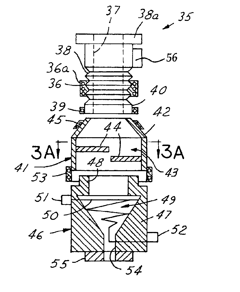
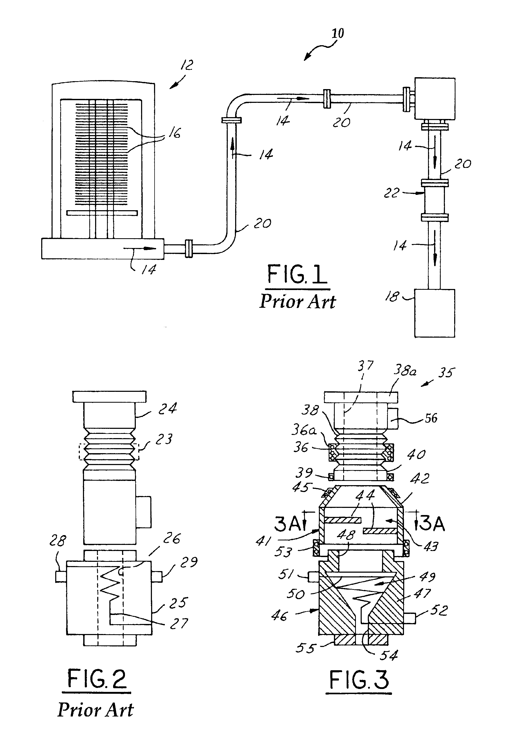
[0032]Referring to FIGS. 3-3B, an illustrative embodiment of the cold trap of the present invention is generally indicated by reference numeral 35 and typically includes a bellow or pipe 38, the upstream inlet end of which may be provided with a pipe flange 38a to facilitate confluent attachment of the cold trap 35 to an exhaust conduit such as the exhaust conduit 20 heretofore described with respect to the silicon nitride deposition system 10 of FIG. 1. A pipe clamp 56 may be provided on the pipe 38 for removable attachment of the...


PUM

PropertyMeasurementUnit
temperatureaaaaaaaaaa

Abstract

A cold trap having improved trapping efficiency for particles, particularly ammonium chloride fine powder particles. The cold trap has a dual-stage design, including an upstream stage fitted with at least one trap plate and a downstream stage fitted with a typically cup- or cone-shaped trap core in which is provided a conically-spiraled water cooling coil. A decreasing temperature gradient is provided along the length of the cold trap, such that exhaust gases flowing through the cold trap are gradually cooled and ammonium chloride or other particles which form from the gas are trapped by the trap plate or plates and collect in the trap core. The exhaust gases exiting the downstream end of the trap core are substantially or completely devoid of particles.

Description

FIELD OF THE INVENTION[0001]The present invention relates to chemical vapor deposition (CVD) chambers used in the deposition of conductive and resistive layers on a semiconductor wafer substrate. More particularly, the present invention relates to a multi-stage cold trap for cooling exhaust gases from a CVD chamber and trapping particulate precipitates in the gas.BACKGROUND OF THE INVENTION[0002]In the semiconductor production industry, various processing steps are used to fabricate integrated circuits on a semiconductor wafer. These steps include the deposition of layers of different materials including metallization layers, passivation layers and insulation layers on the wafer substrate, as well as photoresist stripping and sidewall passivation polymer layer removal. In modern memory devices, for example, multiple layers of metal conductors are required for providing a multi-layer metal interconnection structure in defining a circuit on the wafer. Chemical vapor deposition (CVD) p...

Claims


Application Information

Patent Timeline
Patent Type & Authority Patents(United States)
IPC IPC(8): C23C16/44
CPCC23C16/4412Y10S55/15
Inventor LIN, LEONFAN, TOMCHEN, STEVENLEE, VITOWU, YU-HSIANG
Owner TAIWAN SEMICON MFG CO LTD
Why Eureka
Try Eureka