
Method of manufacturing plastic optical fiber

Inactive Publication Date: 2005-06-21
KURARAY CO LTD
View PDF10 Cites 2 Cited by
  • Summary
  • Abstract
  • Description
  • Claims
  • Application Information

AI Technical Summary

Benefits of technology

[0008]The present invention was made in view of the above problems with an object of providing a drawing method of manufacturing a plastic optical fiber, in which method the plastic optical fiber is produced with a high production speed and with a high quality without blowing bubbles or heat degradation.
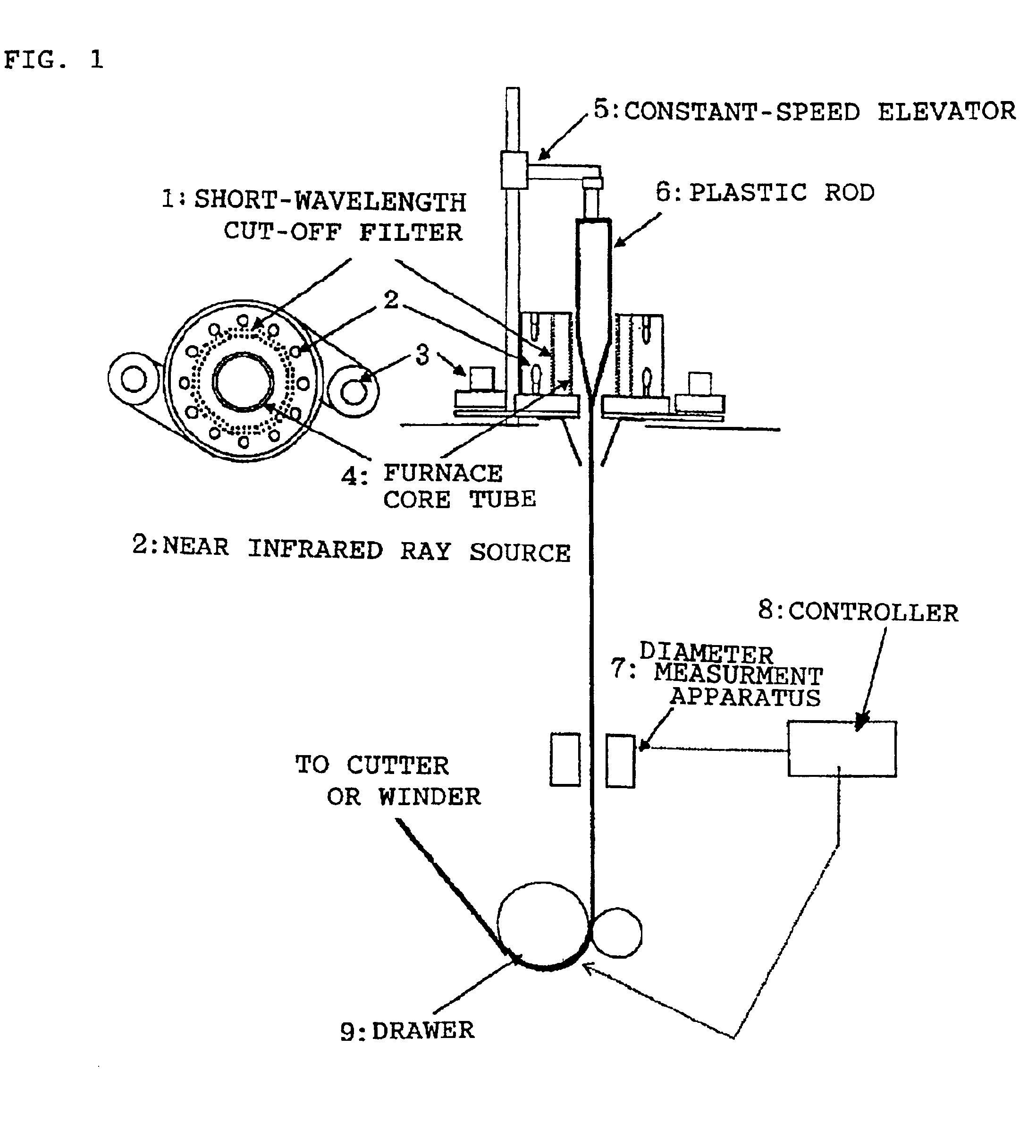
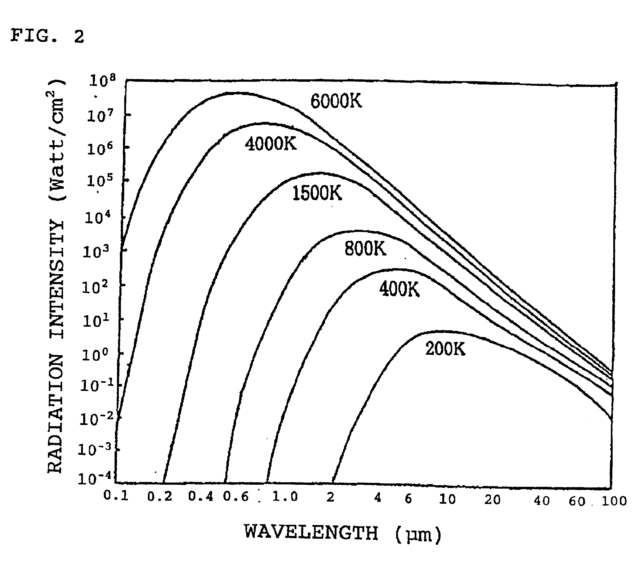
[0012]In the present invention of the method of manufacturing a plastic optical fiber, the near infrared ray source used for heating the transparent plastic rod is preferably a near infrared ray radiating body with color temperature thereof being from 1000 to 4000K for radiating near infrared ray with a wavelength, which is the peak of radiation energy spectrum, being from 0.7 to 3 μm, because, with such near infrared rays, the rod can be uniformly heated so far as inside thereof yet without decreasing heating efficiency. In addition, it is preferable to provide a short-wavelength cut-off filter between the near infrared ray source and the transparent plastic rod to be heated for cutting off light rays with short wavelengths equal to or less than wavelengths of visible light rays or wavelengths of ultraviolet rays. This is because the rod material can be prevented from being deteriorated due to irradiation of visible light rays and ultraviolet rays.

Problems solved by technology

Although an extruding machine used for the melt extrusion spinning method is an apparatus being large sized and expensive, the melt extrusion spinning method is suited for mass production.
However, in the method, the extruding machine takes so a long time from a start of an operation to a steady operation that the method causes large losses in time and material.
Therefore, an attempt of changing material such as a change in kind of resin as a material or a change in kind of additive causes losses due to the change to make the melt extrusion spinning method not always suitable for small-lot production of a wide variety of products.
Although the drawing method is not suited for mass production, it facilitates manufacturing of various kinds of optical fibers having cross sectional forms of not only being circular but also being irregularly shaped such as being rectangular.
When a thick plastic rod is going to be heated by a heater or hot air in the drawing method, this small thermal conductivity causes that the temperature only on the surface is raised and the temperature of the central portion is not raised, thereof the heat can not conduct to the central portion.
Thus, the drawing was made impossible.
When the temperature of the heater or the hot air is raised for raising the temperature of the rod so far as the central portion, only the temperature of the rod surface is excessively raised to cause blowing or heat deterioration on the rod surface.
This will induce defects and nonuniformity in diameter in an optical fiber manufactured from such a rod only to provide the optical fiber as being inferior in light transmission loss.
The use of such a heat source, because of low absorption efficiency in plastic for near infrared rays, necessitates a supply of considerably large power to offer a problem in heating efficiency.

Method used


Image

  • Method of manufacturing plastic optical fiber
  • Method of manufacturing plastic optical fiber
  • Method of manufacturing plastic optical fiber

Examples


example 1

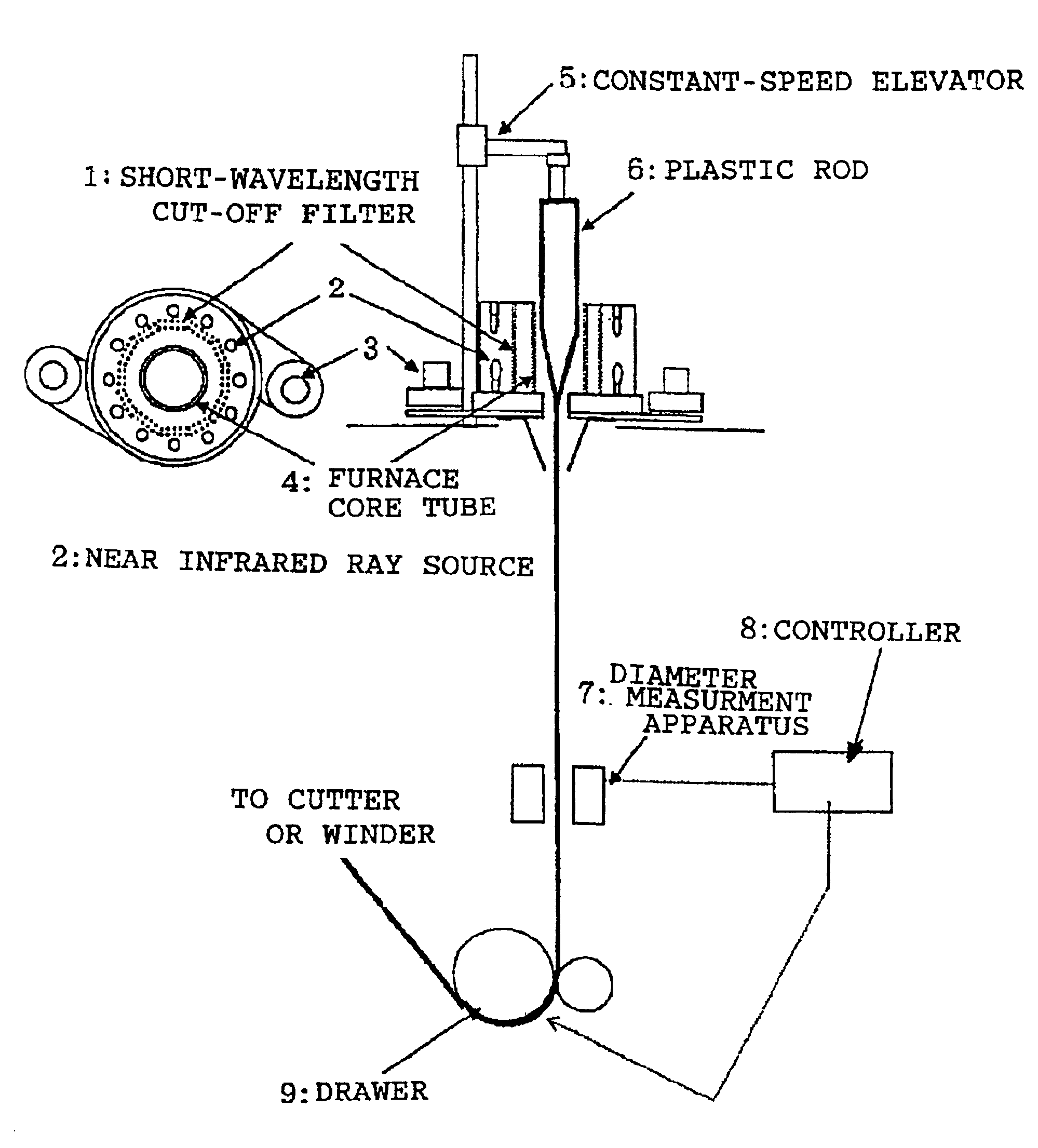
[0031]In the near infrared ray furnace and the drawing apparatus shown in FIG. 1, the near infrared ray sources 2 were provided as two stages of twelve (twenty four in total) halogen lamps (color temperature of 2750K for supply voltage of 100V, lamp supply voltage of 75V, and current of 19.5A) arranged at uniform intervals on a circle with a radius of 120 mm. Inside such an arrangement of halogen lamps, there is mounted an infrared ray transmitting filter (ITF-50S-80IR, manufactured by Sigma Koki Co., Ltd.) with the transmission characteristic shown in FIG. 5. In the apparatus, a rod for a plastic optical fiber with a diameter of 70 mm was set which comprises polystyrene resin (core material) and acrylic resin (cladding material). The top end of thus set rod was introduced into the halogen lamp near infrared ray furnace with a moving down speed of 1.65 mm / min for being heated. The resin, heated, softened and hung down from the rod, was introduced to the drawer (drawing speed of 7.2 ...

example 2

[0032]In the apparatus used for the example 1, a 70 mm diameter rod for a plastic scintillating fiber was introduced which rod comprises polystyrene resin containing fluorescent dyes for a plastic scintillator (core material) and acrylic resin (cladding material). The rod was heated and drawn under a heating condition and with a moving down speed both the same as those for the rod in the example 1. This allowed a 1 mm diameter plastic scintillating fiber to be manufactured without producing any blowing bubbles. Fluorescent dyes contained in the polystyrene resin are 1% of 2-(4-tbutylphenyl)-5-(4-biphenyl)1,3,4 oxadiazole, and 0.02% of 4-4′bis(2,5 dimethyl styryl)diphenyl. In the example 2, a drawing speed at the drawer 9 was 7.5 m / min. The plastic scintillating fiber provided a satisfactory light yield characteristics without any problem with an attenuation length as an index of transparency being superior as 380 cm.

example 3

[0033]In the apparatus used for the example 1, a 100 mm diameter rod for a plastic optical fiber was introduced which rod comprises polystyrene resin (core material) and polymethylmethacrylate resin (cladding material). The rod was heated and drawn to allow a 1 mm diameter plastic optical fiber to be manufactured without producing any blowing. In the example 3, the halogen lamp was operated by a supply voltage of 85V with a current of 22.5A. The moving down speed of the rod was 2.0 mm / min, and the drawing speed at the drawer 9 was 19.5 m / min. The measured transmission loss of the plastic optical fiber was 185 dB / km at the wavelength of 670 nm.


PUM

PropertyMeasurementUnit
Temperatureaaaaaaaaaa
Lengthaaaaaaaaaa

Abstract

In a method of manufacturing a plastic optical fiber by heating and drawing either one end portion of a transparent plastic rod, a plastic optical fiber having a cross sectional form approximately similar to the cross sectional form of the transparent plastic rod, the transparent plastic rod is heated by exposing near infrared ray which is radiated from a near infrared ray source. This can prevent the plastic optical fiber from causing to blow many bubbles on the surface and heat degradation to allow the plastic optical fiber to be obtained with a high quality.

Description

BACKGROUND OF THE INVENTION[0001]1. Field of the Invention[0002]The present invention relates to a method of manufacturing a plastic optical fiber, particularly to a method of manufacturing a plastic optical fiber containing a fluorescent dye.[0003]2. Description of the Related Art[0004]In most of ordinary methods of manufacturing optical fibers, a melt extrusion spinning method is employed in which transparent plastic is molten to be extruded from a narrow nozzle. In an example of the method of manufacturing a plastic optical fiber employing the melt extrusion spinning method, methylmethacrylate monomer is subjected to bulk polymerization, for example, for being continuously extruded as a fiber without passing through a process of being formed in pellets. Although an extruding machine used for the melt extrusion spinning method is an apparatus being large sized and expensive, the melt extrusion spinning method is suited for mass production. However, in the method, the extruding mac...

Claims


Application Information

Patent Timeline
IPC IPC(8): B29D11/00B29C55/06G02B6/00
CPCB29D11/00721
Inventor SAITO, KATASHISHINJI, OSAMU
Owner KURARAY CO LTD
Learn More