Visible radiation type photocatalyst and production method thereof

Inactive Publication Date: 2005-06-21
ASUKATEC
View PDF18 Cites 44 Cited by
  • Summary
  • Abstract
  • Description
  • Claims
  • Application Information

AI Technical Summary

Problems solved by technology

However, this method is practically unfeasible because it involves the use of voluminous equipment.
How

Method used


Image

  • Visible radiation type photocatalyst and production method thereof
  • Visible radiation type photocatalyst and production method thereof
  • Visible radiation type photocatalyst and production method thereof

Examples


example 2

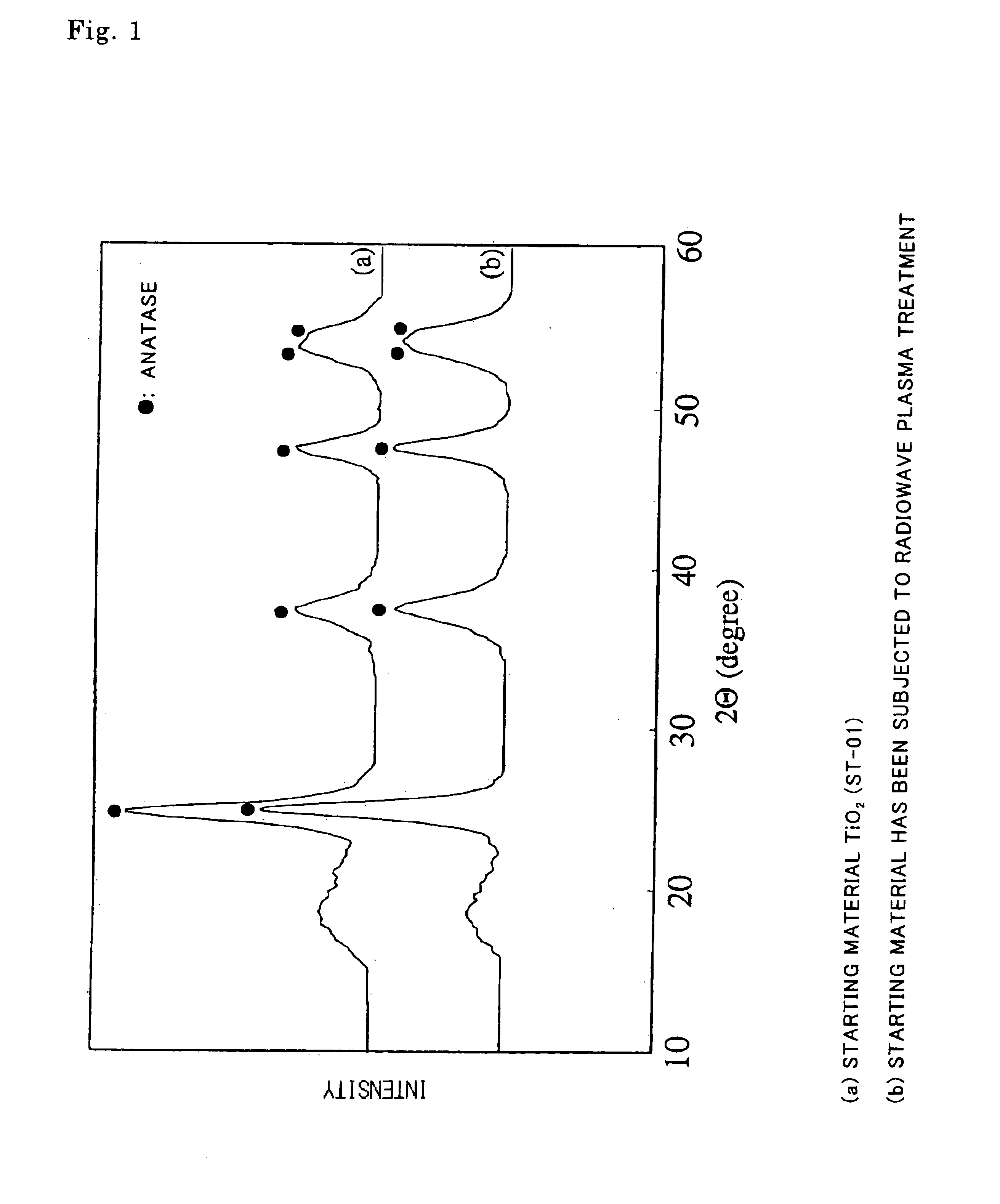
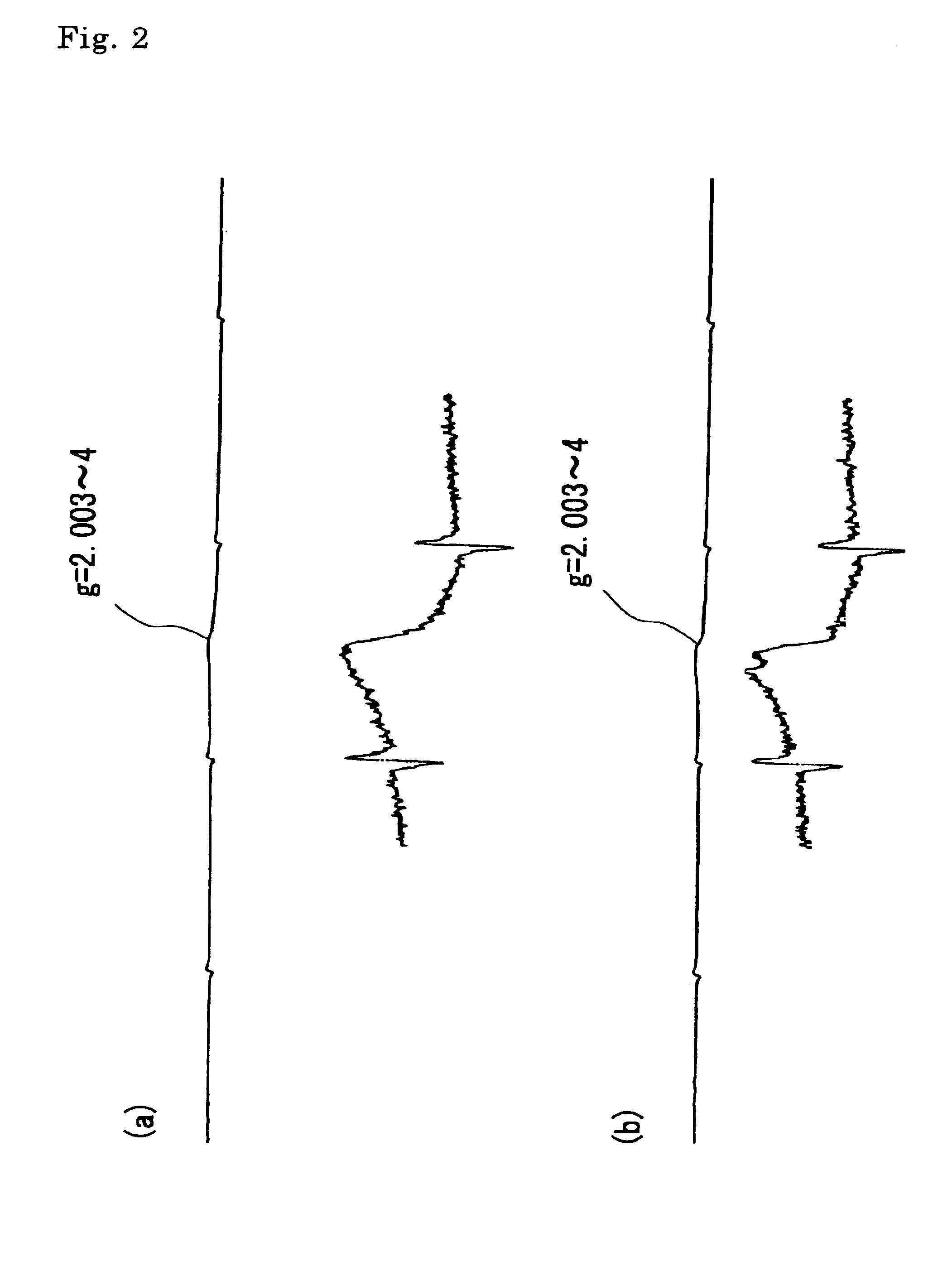
[0064]A 10-g portion of a powder (60 mesh or less in granularity) of an anatase type titanium dioxide was placed inside a 200-ml volume quartz reaction tube. The quartz reaction tube was connected to a plasma generating apparatus, and after evacuating the inside of the system by using a vacuum pump, a 400-W power electromagnetic wave (at a frequency of 2.45 GHz) was irradiated to the powder of anatase type titanium dioxide placed inside the reaction tube to thereby generate a plasma by using a Tesla coil. Then, gaseous argon was introduced inside the system at a flow rate of 10 ml / min to set the pressure inside the system to about 1 Torr. The treatment was continued for 120 minutes while stirring the anatase type titanium dioxide powder placed inside the reaction tube.

[0065]Time duration of 40 minutes was necessary to increase the vacuum degree inside the plasma treatment system for 1 Torr without introducing a gas and while cutting off the pump evacuation. The anatase type titanium...

example 3

[0068]A production method of a catalyst according to the present invention comprising injecting ions of rare gas elements to the surface of an oxide semiconductor, an anatase type titanium dioxide, is described below.

[0069]As the equipment was used a medium current ion implantation apparatus, ULVAC IKX-7000 manufactured by ULVAC Co., Ltd.

[0070]The method comprises, after introducing gaseous argon, irradiating electron beam to the sample for ionization, subjecting the ionized species to mass spectroscopy to separate and take out argon ions, and the argon ions were accelerated in an accelerator (at a direct current voltage of 100 kV) to inject argon ions to the target.

[0071]As the target, a glass plate 6 cm in diameter (which is about 0.2 mm in thickness and which is coated with a carbon film at a thickness of less than 1 Mm in order to ensure conductivity necessary for an ion implantation method) coated with 0.2 g of ST-01 was used.

[0072]Argon ions were injected at a density of 5 ×10...

example 1

[0077]

TABLE 1Halogen Lamp(with radiations 420 nm orTime duration of lightshorter in wavelength cut off)irradiation (minutes)Example 1400 ppm120Example 2330 ppm90Example 3520 ppm60Comparative Ex- 0 ppm120ample 1

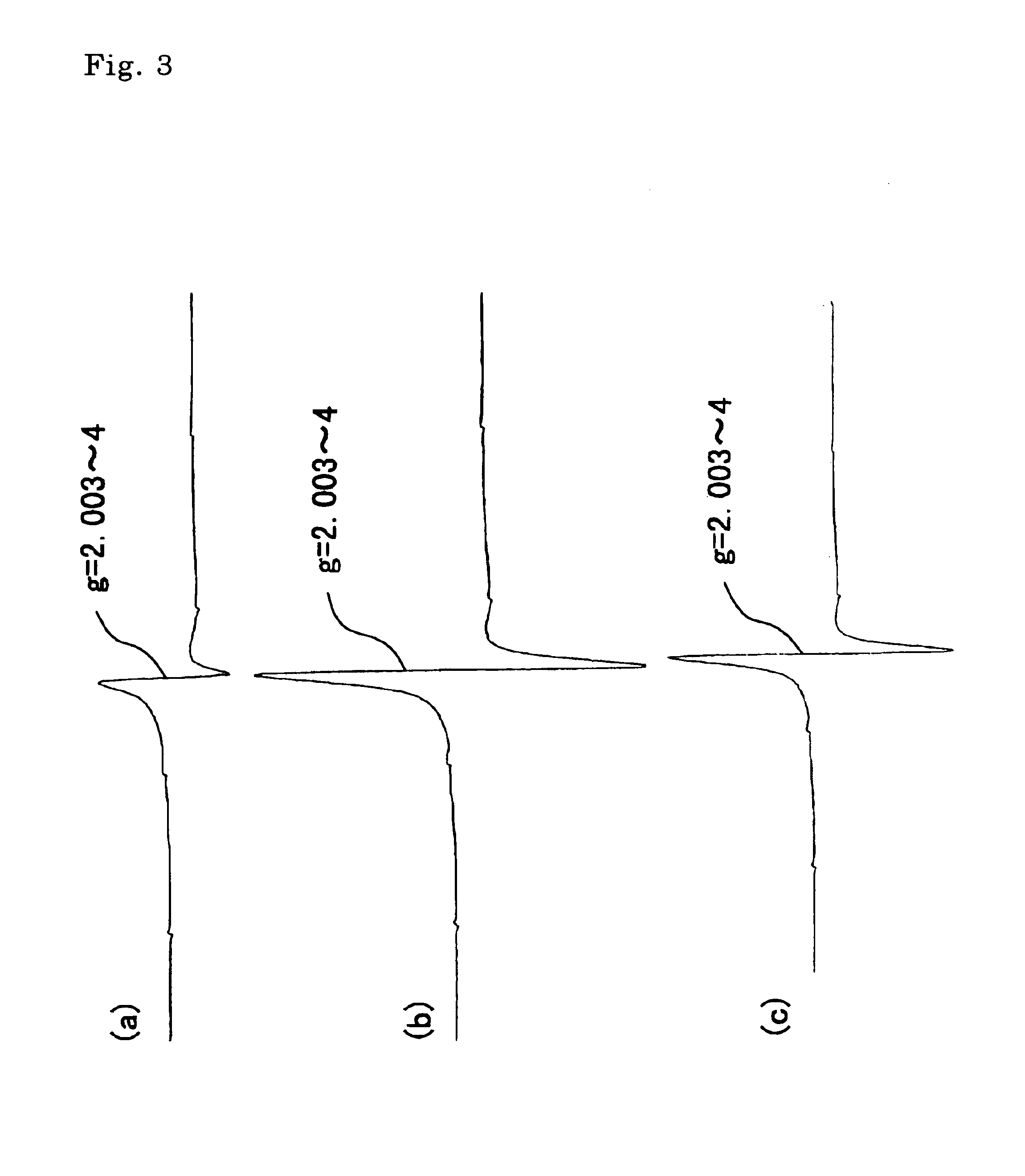
[0078]From the results shown in Table 1, it can be understood that the photocatalysts according to the present invention, which are each anatase type titanium dioxide and which contain stable oxygen defects, exhibit high ability in the photodecomposition of acetaldehyde under irradiation of a visible light. Furthermore, the material used in Comparative Example 1 shows high adsorption to acetaldehyde, but had no photodecomposition effect under the irradiation of a visible light.


PUM

PropertyMeasurementUnit
Timeaaaaaaaaaa
Pressureaaaaaaaaaa
Diameteraaaaaaaaaa

Abstract

The invention is directed to a catalyst having activity under the irradiation of a visible light, the catalyst being an oxide semiconductor such as an anatase type titanium dioxide, having stable oxygen defects. A method for producing a catalyst having activity under the irradiation of a visible light which comprises treating an oxide semiconductor with hydrogen plasma or with a plasma of a rare gas element, comprising performing the treatment in a state substantially free from the intrusion of air into the treatment system is also provided. An article comprising a base material having the catalyst above provided on the surface thereof and a method for decomposing a substance, comprising bringing an object to be decomposed into contact with the catalyst above under the irradiation of a light containing at least a visible radiation are disclosed. A novel photocatalyst which enables use of a visible radiation is provided, as well as a method utilizing the photocatalyst for removing various substances containing an organic matter or bacteria by photodecomposition.

Description

BACKGROUND OF THE INVENTION[0001]1. Field of the Invention[0002]The present invention relates to a photocatalyst having a visible light activity, to a method for producing the photocatalyst, a method of photodecomposition using a light involving visible rays, and to a device using the photocatalyst.[0003]2. Background Art[0004]Various studies on deodorization and sterilization using photocatalysts have been made to present, and some of them have been put to practice. For instance, in WO94 / 11092 is disclosed a method for treating air using a photocatalyst under the irradiation of room light. In Japanese Patent Laid-Open No. 102678 / 1995 is disclosed a method for preventing medical infection from occurring in hospitals by using photocatalysts. In both cases, an oxide semiconductor such as titanium dioxide and the like is used as the photocatalyst, which requires an ultraviolet radiation 400 nm or shorter in wavelength for the excitation.[0005]However, sunlight or an artificial light so...

Claims


Application Information

Patent Timeline
IPC IPC(8): B01D53/86B01J37/34B01J35/00B01J37/00C01G23/00C01G23/04H01G9/20
CPCB01D53/8678B01J35/002B01J35/004B01J37/349C01G23/043H01G9/2031B82Y30/00B01D2255/802B01D2257/404Y02E10/542C01P2002/72C01P2002/86C01P2004/64Y02W10/37Y02P70/50B01J21/063B01J35/023C01G23/047
Inventor SUGIHARA, SHINICHI
Owner ASUKATEC
Why Eureka
Try Eureka