Surface for use on implantable device

a technology for implantable devices and surfaces, applied in the field of improved irregular surfaces, can solve the problems of implant having a smooth surface, pain and danger for patients, and cement tending to deteriorate, and achieve the effects of reducing air resistance, increasing electromagnetic radiation absorbability, and large surface area

Inactive Publication Date: 2005-06-28
TITAN SPINE
View PDF9 Cites 59 Cited by
  • Summary
  • Abstract
  • Description
  • Claims
  • Application Information

AI Technical Summary

Benefits of technology

[0015]An attachment surface is provided in which a random irregular pattern is formed through a repetitive masking and chemical milling process. In some applications, such as the affixation of a composite material to a rigid or metallic substrate, the malleable composite material is molded into the irregularities of the substrate. As utilized in the production of some aircraft components, for example, a malleable, composite surface material is deposited upon a metal superstructure, which provides strength and support. The composite outer layer is designed to provide external characteristics, such as r

Problems solved by technology

One of the significant shortcomings of a cement adhesion of the two elements is that over time, the cement tends to deteriorate.
In either event, the result is painful and dangerous to the patient.
An additional problem which has occurred with relation to the ingrowth embodiment relates to the preparation of the surface of the implant.
An implant having a smooth surface is inappropriate for use in this type of operation as it provid

Method used


Image

  • Surface for use on implantable device
  • Surface for use on implantable device
  • Surface for use on implantable device

Examples


Embodiment Construction

A. Chemical Etching Embodiments:

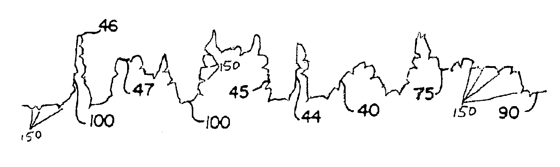
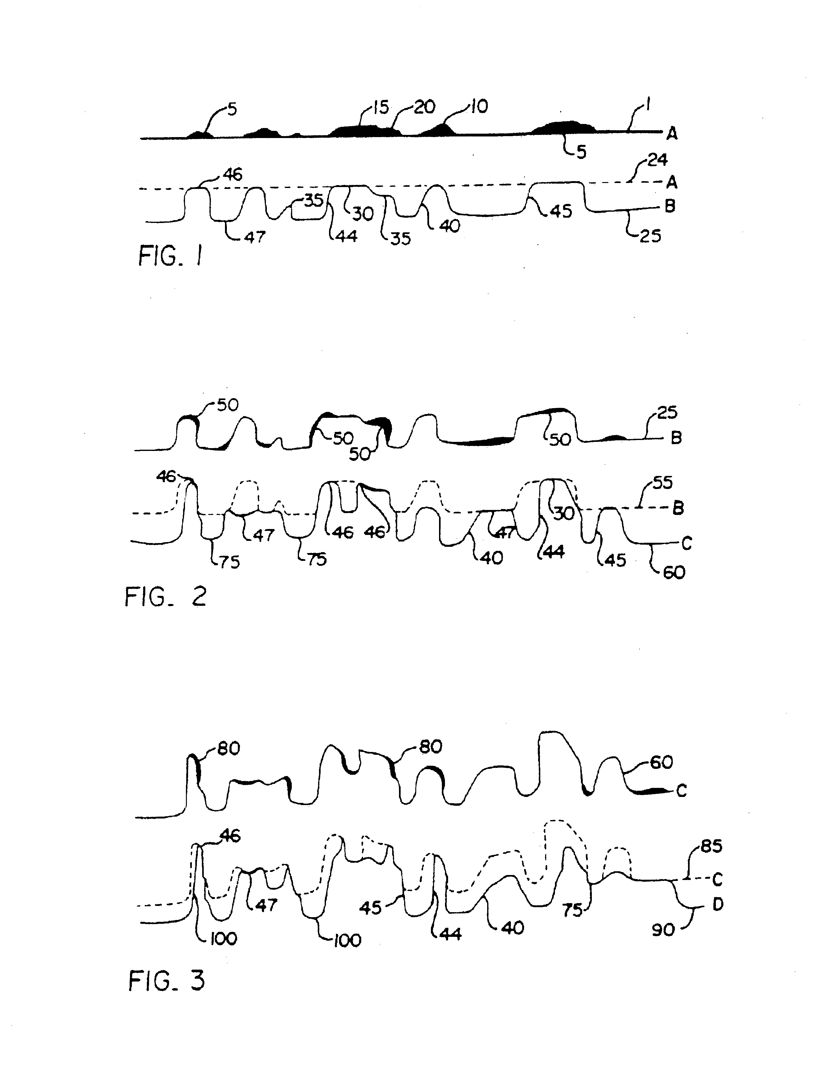
[0034]In describing the preferred embodiment of the invention when chemical etching is employed and the best mode of carrying the invention out, the drawings and description refer to the use of a titanium alloy base metal. While titanium is the preferred embodiment for the implantable material, a number of other alloys may be utilized. Each of these different alloys will require a different maskant and etchant composition. Other than cobalt chromium, no specific details are given in the specification regarding the use of these other metals and etchants. It is, however, considered to be well within the knowledge of an experienced practitioner in the art to select an etchant once a base alloy has been identified. Furthermore, for the purposes of clarity, certain repetitive elements in the drawings have not been numerically identified for each and every occurrence. For example, a number of maskant points are shown on the surface diagrams. It is considere...


PUM

PropertyMeasurementUnit
Lengthaaaaaaaaaa
Lengthaaaaaaaaaa
Fractionaaaaaaaaaa

Abstract

An attachment surface for an implantable device has an irregular pattern formed through a process including masking, chemical or electrochemical etching, blasting and debris removal steps. Surface material is removed from the implant surface without stress on the adjoining material and the process provides fully dimensional fillet radii at the base of the surface irregularities. This irregular surface is adapted to receive the ingrowth of bone material and to provide a strong anchor for that bone material which is resistant to cracking or breaking. The surface is prepared through an etching process which utilizes the random application of a maskant and subsequent etching in areas unprotected by the maskant. This chemical etching process is repeated a number of times as necessitated by the nature of the irregularities required in the surface. The blasting and debris removal steps produce microfeatures on the surface that enhance the ingrowth of bone material.

Description

BACKGROUND OF THE INVENTION[0001]1. Field of the Invention[0002]The present invention relates to an improved irregular surface which may be utilized in conjunction with a bone implant to facilitate the growth of bone tissue within the surface. The invention also relates to a method of production of this surface. The irregular surface is created on a substrate material to particularly adapt that surface for joining to a second material. More specifically, the invention relates to the sequential etching of a bone implant surface to produce an irregular random pattern of protrusions and depressions through the use of chemical and electrochemical milling techniques and the subsequent blasting of the surface to produce micro features on the surface.[0003]2. Description of the Prior Art[0004]In the field of bone implantation, or the use of man-made objects to replace portions of bone within the human body, there are two primary methods of affixing the implant device to the existing bone. ...

Claims


Application Information

Patent Timeline
IPC IPC(8): A61F2/00A61F2/30A61F2/28A61F2/02B08B7/00B44C1/22B32B3/30D06N7/00D06N7/04A61BA61L27/32A61L27/50C09J5/02C23F1/02C23F1/04H05K3/38H05K3/44
CPCA61F2/30767A61L27/32A61L27/50C09J5/02C23F1/02C23F1/04A61F2/30771A61F2/28Y10T428/24355A61F2/3094A61F2002/30719A61F2002/30838A61F2002/30906A61F2002/30925A61F2002/30927A61F2250/0092A61F2310/00023A61F2310/00029A61F2310/00796A61L2400/18A61L2430/02C09J2400/166H05K3/382H05K3/44Y10S623/92Y10S623/901
Inventor WAGNER, DONALD J.WAGNER, II, DONALD J.BRISTOL, RODNEY
Owner TITAN SPINE
Why Eureka
Try Eureka