

Continuous carbonylation process
a carbonylation process and process technology, applied in the preparation of carboxylic compounds, carboxylic preparations from carbon monoxide reactions, organic chemistry, etc., can solve the problems of solid phase catalysts, serious catalyst precipitation, and rhodium catalyst precipitation, so as to reduce or eliminate the need for catalyst recovery, and reduce the effect of heat removal efficiency
- Summary
- Abstract
- Description
- Claims
- Application Information
AI Technical Summary
Benefits of technology
Problems solved by technology
Method used
Image


Examples
example 1
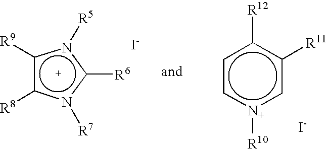
[0042]This example illustrates the carbonylation of methanol in the presence of rhodium, 1-butyl-3-methylimidazolium iodide ionic liquid and water at elevated pressure utilizing the process of the invention. The reactor was loaded with the 1-butyl-3-methylimidazolium iodide (14.45 g, 10 mL), rhodium trichloride hydrate (83.7 mg, containing 40.01 wt % Rh) and water (2 mL) through the top of the reactor with carbon monoxide flowing at 50 standard cubic centimeters per minute (SCCM) through the base of the reactor. Carbon monoxide flows were maintained until the catalyst was removed from the reactor to prevent seepage of the liquid below the 5-micron sintered Hastelloy C alloy filter that acted as a gas dispersion and catalyst support device. A Hastelloy C alloy thermowell extending from the top of the reactor to the bottom 5-micron sintered Hastelloy C alloy filter was attached to the top of the vertical loading and sensing tube, and a pressure transducer was attached to the pressure ...
example 2
[0044]This example illustrates the carbonylation of methanol in the presence of rhodium, 1-butyl-3-methylimidazolium iodide ionic liquid in the absence of water at elevated pressure at various feed rates utilizing the process of the invention. The ionic liquid containing the rhodium catalyst used in Example 1 was retained in the reactor. The liquid feed consisted of methanol / methyl iodide in a weight ratio of 70 / 30 and had a density=1.0 g / mL. Liquid feed rate, carbon monoxide feed rate and the temperature of the ionic liquid (melt temp.) are provided in Table 2. Set temperatures and attained pressures were as per Example 1.
[0045]
TABLE 2ExamplemL LiquidNumberFeed / MinuteSCCM COMelt Temp., ° C.2-10.253721922-20.253001942-30.384502002-40.384502002-50.131501902-60.131501882-70.131501882-80.131501902-90.13150189 2-100.13150189 2-110.13150188 2-120.13150190 2-130.13150190
[0046]The corresponding methanol conversions, moles HOAc produced / L-hr and MeOAc produced / L-hr are provided in Table 3.
[...
example 3
[0049]Example 3 illustrates the carbonylation of methanol in the presence of water at elevated pressure using an iridium catalyst dissolved in an ionic liquid consisting of 1-butyl-3-methylimidazolium iodide and zinc iodide. Zinc iodide (8.53 g), 1-butyl-3-methylimidazolium iodide (7.23 g), iridium trichloride hydrate (106.1 mg, 54.36 wt % Ir) and water (3 mL) were added to the reactor described in Example 1. The volume of the zinc iodide / 1-butyl-3-methylimidazolium iodide mixture was 7 mL. The reactor was brought to reaction pressure and temperature as per Example 1. After the reactor melt had reached 180° C. the CO flow was increased to 300 SCCM. A solution consisting of methanol / methyl iodide / water in a weight ratios of 67 / 29 / 4 was fed to the reactor system at 0.25 mL / minute. The density of the liquid feed system was 1.0 g / mL. The pressure in the reactor ranged between 200 and 210 psig (13.8 and 14.5 barg). After the liquid feed was started, the melt temperature increased to 186-...
PUM
| Property | Measurement | Unit |
|---|---|---|
| molar ratio | aaaaa | aaaaa |
| molar concentration | aaaaa | aaaaa |
| molar ratio | aaaaa | aaaaa |
Abstract
Description
Claims
Application Information