
Resistive heaters and uses thereof

a technology of resistive heaters and heaters, which is applied in the direction of resistive material coating, lining repair, drying machines with progressive movements, etc., can solve the problems of more difficult to form elements, low resistivity of layers, etc., to prevent bending or fracture of different layers, improve adhesion, and improve thermal matching

Inactive Publication Date: 2005-07-19
REGAL WARE
View PDF86 Cites 75 Cited by
  • Summary
  • Abstract
  • Description
  • Claims
  • Application Information

AI Technical Summary

Benefits of technology

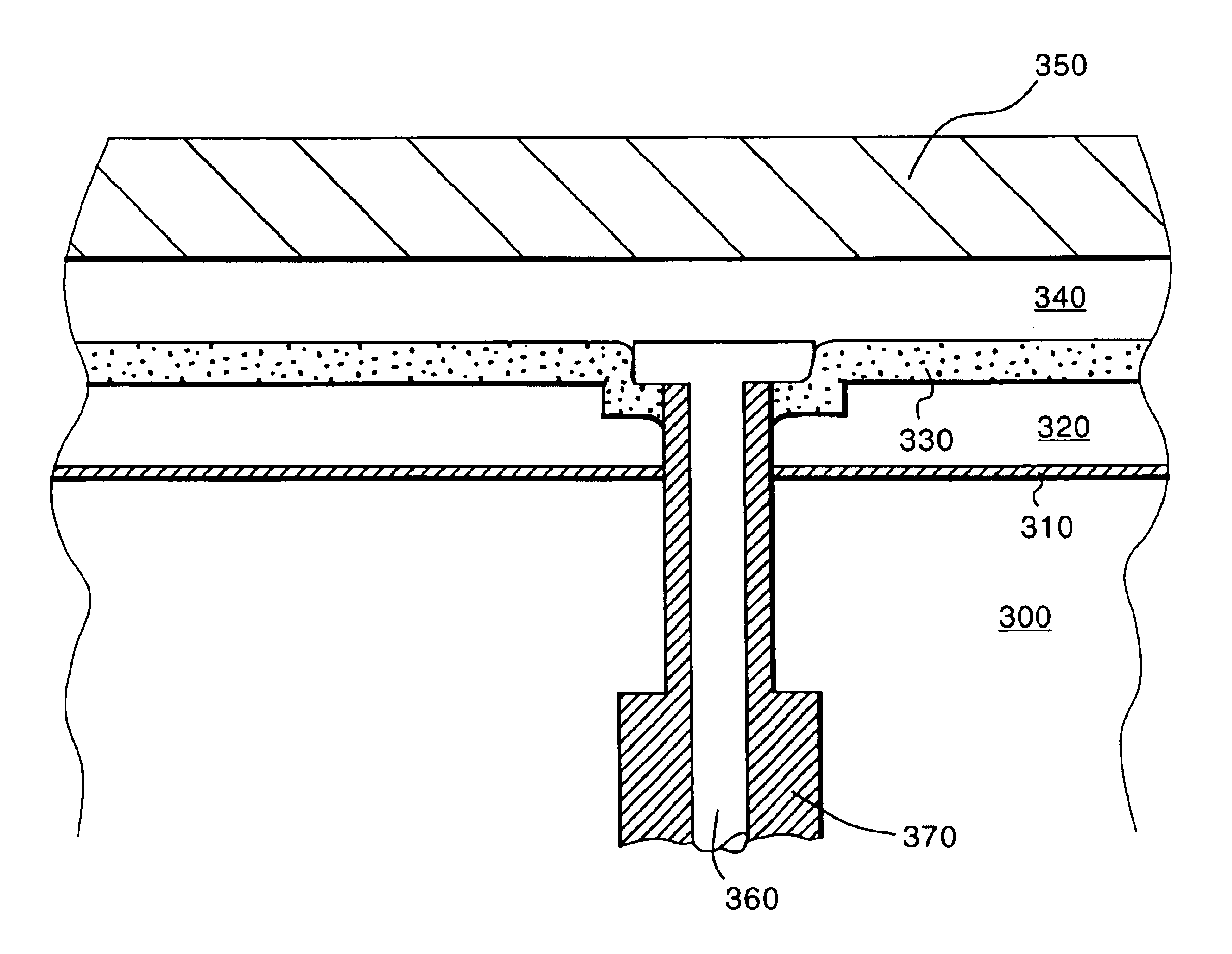
[0026]A particular embodiment of the invention includes the use of insulating layers positioned above or below the heater to insulate the resistive layer electrically from adjacent, electrically conductive components. Additional layers can be added to reflect or emit heat from the heater in a selected pattern. One or more layers can also be included to provide improved thermal matching between components to prevent bending or fracture of different layers having different coefficients of thermal expansion. Layers that improve the adhesion between layers and the substrate may also be used.

Problems solved by technology

When nickel-chrome is deposited as a resistive heater, however, the bulk resistivity of the layer is still rather low, which makes it more difficult to form an element because a long path length is required to achieve a high enough resistance.

Method used


Image

  • Resistive heaters and uses thereof
  • Resistive heaters and uses thereof
  • Resistive heaters and uses thereof

Examples


Embodiment Construction

[0039]We have discovered a metallic resistive layer (and methods of making same) that includes a metallic component that is electroconductive and an oxide, nitride, carbide, and / or boride derivative of the metal component that is electrically insulating. We have further discovered that this resistive layer, when coupled to a power supply, functions as a heater.

[0040]To deposit a layer that will generate heat when a voltage is applied, the layer must have a resistance that is determined by the desired power level. The resistance, R, is calculated from the applied voltage, V, and the desired power level, P, from:

R=V2 / P

[0041]The resistance is related to the geometry of the heater coating—the electric current path length, L, and the cross sectional area, A, through which the current passes—and also to the material resistivity, ρ, by the equation:

R=ρL / A

[0042]Therefore, to design a layer for a given power level and a given geometry that will operate at a given voltage, one has only to det...


PUM

PropertyMeasurementUnit
Adhesion strengthaaaaaaaaaa
Metallic bondaaaaaaaaaa
Electrical resistivityaaaaaaaaaa

Abstract

A metallic resistive heater and a method of production are described. The resistive heater has a metallic component that is electrically conductive (i.e. has low resistivity) and an oxide, nitride, carbide, and or boride derivative of the metallic component that is electrically insulating (i.e., has high resistivity). The resistivity is controlled by controlling the amount of oxide, nitride, carbide, and boride formation during the deposition of the metallic component and the derivative.

Description

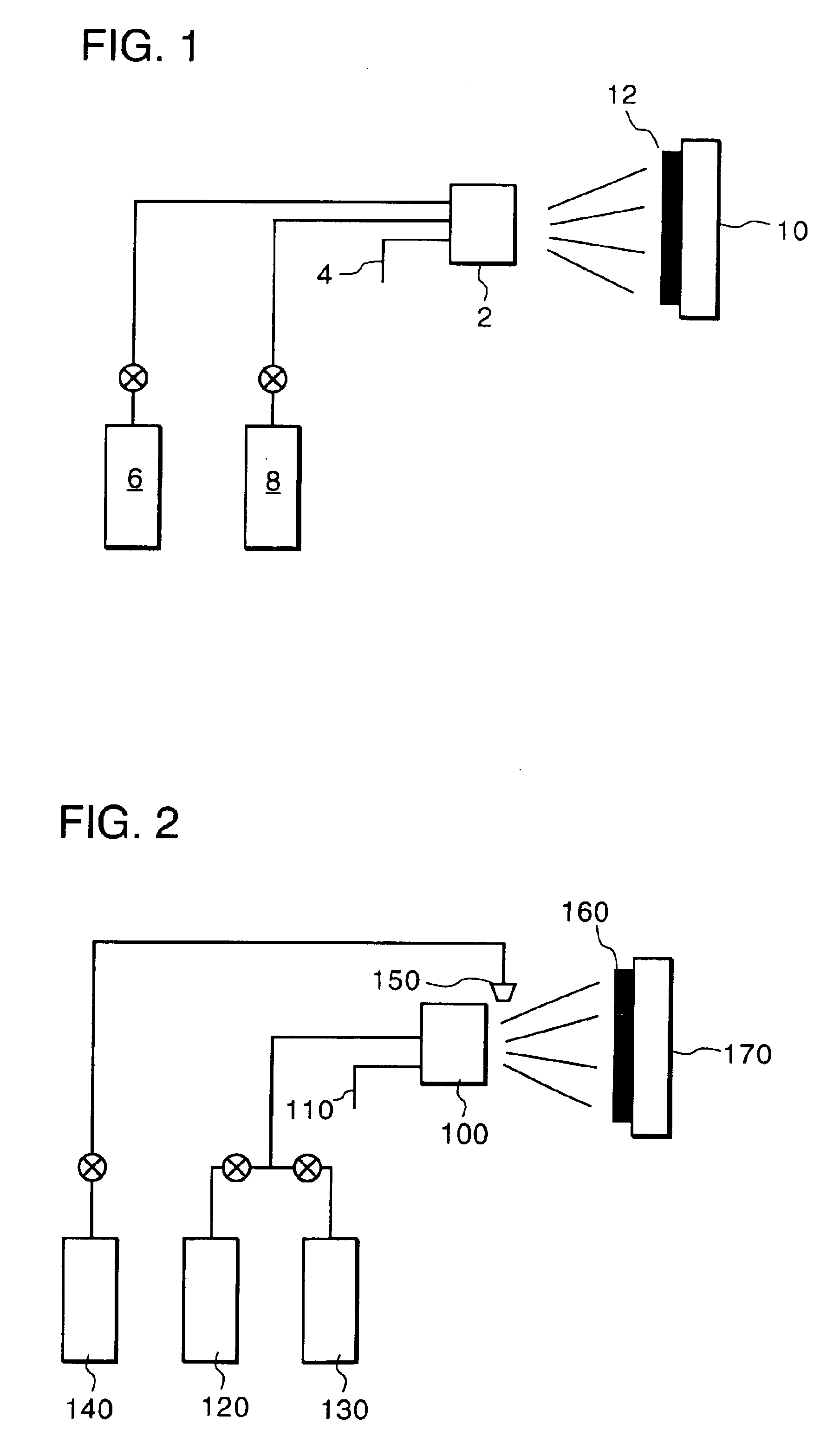
CROSS REFERENCE TO RELATED APPLICATIONS[0001]This application claims benefit of co-pending U.S. Provisional Application Ser. No. 60 / 253,969, filed Nov. 29, 2000, hereby incorporated by reference.BACKGROUND OF THE INVENTION[0002]The invention relates to the field of resistive heaters.Thermal Spray[0003]Thermal spray is a versatile technology for depositing coatings of metals or ceramics. It includes systems that use powder as feedstock (e.g., arc plasma, flame spray, and high velocity oxy-fuel (HVOF) systems), and systems that use wire as feedstock (e.g., arc wire, HVOF wire, and flame spray systems).[0004]Arc plasma spraying is a method for depositing materials on various substrates. A DC electric arc creates an ionized gas (a plasma) that is used to spray molten powdered materials in a manner similar to spraying paint.[0005]Arc wire spray systems function by melting the tips of two wires (e.g., zinc, copper, aluminum, or other metal) and transporting the resulting molten droplets b...

Claims


Application Information

Patent Timeline
IPC IPC(8): B29C45/73C23C4/12C23C4/02H01L21/00H05B3/12B21B27/06B21B27/08F27D1/16H05B3/20B22C9/06B22D17/22C23C4/06C23C4/10C23C16/46F26B13/04H01L21/31H05B3/00H05B3/10H05B3/14H05B3/68
CPCB29C45/73C23C4/02C23C4/12H01L21/67103H05B3/12C23C4/121B21B2027/086Y10T29/49099F27D1/1636C23C4/123Y02T50/60
Inventor ABBOTT, RICHARD C.MAGNANT, GARY P.GLENN, WILLIAM A.
Owner REGAL WARE
Learn More