Gas separation method and device

a gas separation and gas technology, applied in the direction of separation process, dispersed particle separation, chemistry apparatus and processes, etc., can solve the problems of difficult enrichment of psa, difficult to achieve separation, and high cost of krypton and xenon

Inactive Publication Date: 2005-08-02
NIPPON SANSO CORP
View PDF16 Cites 12 Cited by
  • Summary
  • Abstract
  • Description
  • Claims
  • Application Information

AI Technical Summary

Benefits of technology

[0015]The gas separation method of the present invention is a method in which principal gas components are separated from a feed gas that includes at least a first gas component and a second gas component using a pressure swing adsorption method, comprising: a first separation step in which the first gas component is separated as a first gas product by using a first adsorbent that easily adsorbs the first gas component and hardly adsorbs the second gas component; and a second separation step in which the second gas component is separated as a second gas product by using a second adsorbent that easily adsorbs the first gas component and hardly adsorbs the second gas component; wherein in the first and second separation steps, a circulating feed gas is used as the gas to be separated, where the circulating feed gas consists of recovered discharge gases that are discharged when the adsorbents are regenerated and the feed gas; and based on at least one of the component concentrations in the circulating feed gas and the pressure of the gas delivery path, the second gas product is extracted at a constant outflow rate and component concentration by controlling the outflow rate of the first gas product.
[0019]The gas separation apparatus of the present invention is an apparatus that separates principal gas components from a feed gas that includes at least a first gas component and a second gas component by using a pressure swing adsorption method, comprising: a feed gas storage tank into which the feed gas flows, a compressor for compressing a circulating feed gas from the feed gas storage tank, a first separation unit having a first adsorption column for separating the first gas component in the circulating feed gas from the compressor as a first gas product, and a second separation unit having a second adsorption column that separates a second gas component in the circulating feed gas as a second gas product; and the gas separation apparatus being formed such that: a first adsorbent that hardly adsorbs the first gas component and easily adsorbs the second gas component is used in a first adsorption column; a second adsorbent that easily adsorbs the first gas component and hardly adsorbs the second component gas is used in a second adsorption column; the circulating feed gas, consisting of recovered discharge gases that are discharged when these adsorbents are regenerated and are mixed with the feed gas, flows into the first or second adsorption columns as gas to be separated; and based on at least one of the component concentration in the circulating feed gas and the pressure of the gas delivery path, it is possible to adjust the outflow rate of the first gas product.
[0020]The gas separation apparatus of the present invention is an apparatus that separates principal gas components from a feed gas that includes at least a first gas component and a second gas component by using a pressure swing adsorption method, comprising: a feed gas storage tank into which the feed gas flows, a compressor that compresses the circulating feed gas from the feed gas storage tank, a first separation unit having a first adsorption column that separates a first gas component in the circulating feed gas from the compressor as a first gas product, and a second separation unit having a second adsorption column that separates a second gas component in the circulating feed gas as a second gas product; and the gas separation apparatus being formed such that: a first adsorbent that hardly adsorbs the first gas component and easily adsorbs the second gas component is used in the first adsorption column; a second adsorbent that easily adsorbs the first gas component and hardly adsorbs the second gas component is used in the second adsorption column; the circulating feed gas, consisting of the recovered discharge gases that are discharged when these adsorbents are regenerated and the feed gas, flows into the first or second adsorption columns as gas to be separated; a second gas component can be supplied to the circulating feed gas from the outside; and based on at least one of the outflow rate and the component concentration of the first gas product, it is possible to adjust the flow rate of a second gas component supplied from the outside.
[0021]The gas separation apparatus of the present invention is an apparatus that separates principal gas components from a feed gas that includes at least a first gas component and a second gas component by using a pressure swing adsorption method, comprising: a feed gas storage tank into which the feed gas flows, a compressor for compressing the circulating feed gas from the feed gas storage tank, a first separation unit having a first adsorption column that separates the first gas component in the circulating feed gas from the compressor as a first gas product; and a second separation unit having a second adsorption column that separates the second gas component in the circulating feed gas as a second gas product; the gas separation apparatus being formed such that: a first adsorbent that hardly adsorbs the first gas component and easily adsorbs the second gas component is used in the first adsorption column; a second adsorbent that easily adsorbs the first gas component and hardly adsorbs the second component gas is used in the second adsorption column; the circulating feed gas, consisting of the recovered discharge gases that are discharged when these adsorbents are regenerated and the feed gas, flows into the first or second adsorption columns as gas to be separated; a second gas component can be supplied to the circulating feed gas from the outside; and based on at least one of the component concentration in the circulating feed gas and the pressure of the gas delivery path, adjusting the outflow rate of a second gas product supplied from the outside.
[0022]The gas separating apparatus of the present invention is structured so that it is possible to return a first gas product and / or a second gas product to a circulating feed gas based on the outflow rate of at least one of the first gas product and the second gas product.

Problems solved by technology

Krypton and xenon are extremely expensive, since the existence ratio of them in air is very small and the process to separate them from air is complicated, so that the semiconductor manufacturing processes using the rare gases are economically feasible, only on the premise that used gases are recovered, circulated and reused.
However, enriching a valuable rare gas in the rare gas enriching PSA, becomes difficult, and the component concentration of the valuable rare gas extracted as product decreases.
However, increasing the valuable rare gas concentration becomes difficult for the nitrogen enriching PSA and the component concentration of the valuable rare gas in the nitrogen increases, which in turn means that the recovery rate of the valuable rare gas decreases.

Method used


Image

  • Gas separation method and device
  • Gas separation method and device
  • Gas separation method and device

Examples


example 1

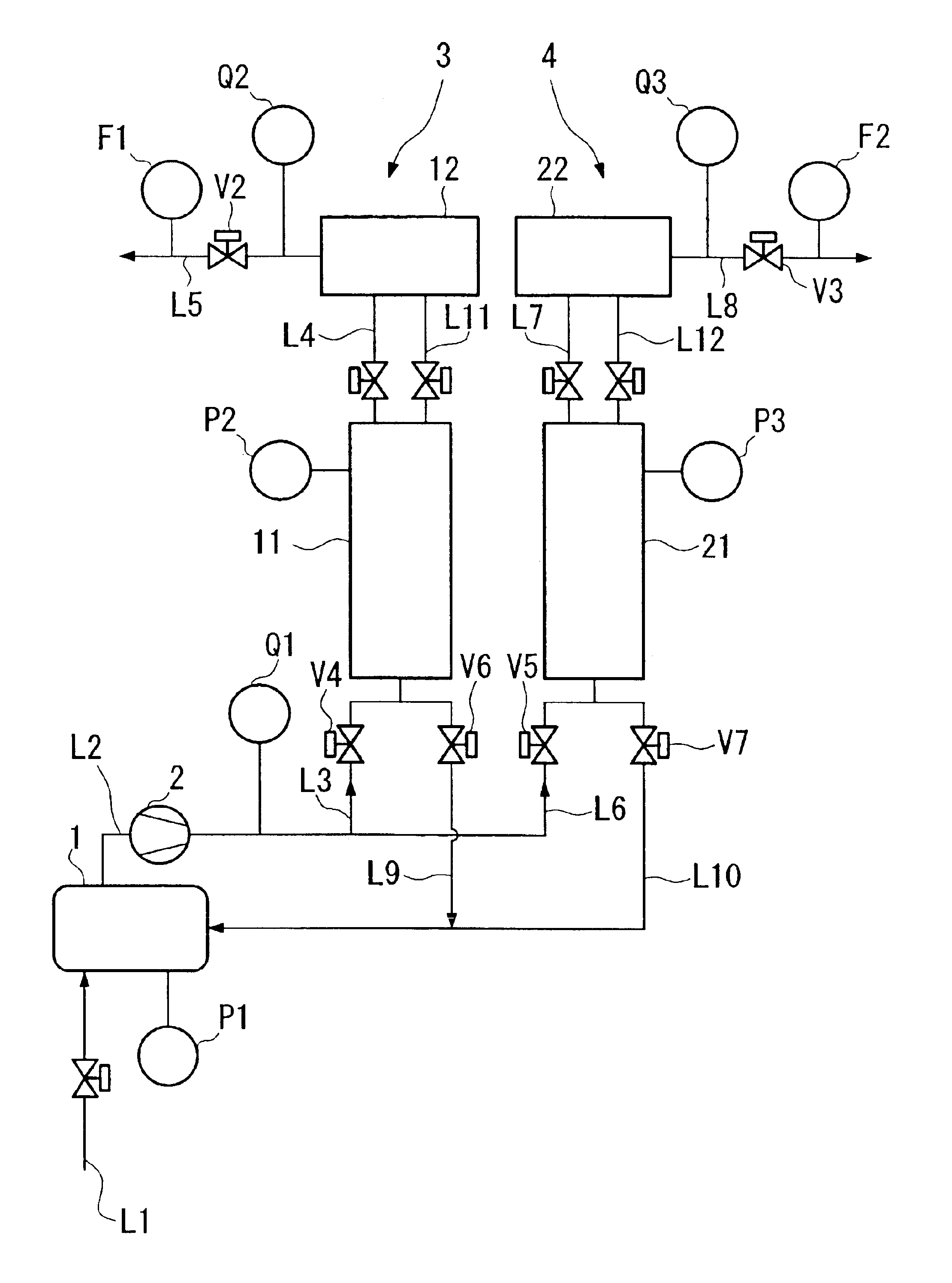
[0088]Separation of krypton and nitrogen was carried out using the gas separation apparatus shown in FIG. 1.

[0089]The first adsorption column 11 had an inner diameter of 108 mm, a height of 650 mm, and was filled with 2.5 kg of activated carbon.

[0090]The second adsorption column 21 had an inner diameter of 154 mm, a height of 650 mm, and was filled with 8.8 kg of an Na-A type zeolite.

[0091]A compressor 2 having a capacity of 26 L / min was used (here and below, the flow rate unit (L / min) is at 0° C. at 1 atmosphere). The operational half-cycle of PSA is 250 s.

[0092]At the start, a mixed gas consisting of 50% krypton and 50% nitrogen was introduced as the feed gas into the apparatus at 2.0 L / min via path L1, and nitrogen product was extracted at 1.005 L / min from path L5 and krypton product was extracted at 0.995 L / min from the path L8.

[0093]First, in order to investigate dependence of the nitrogen product and krypton product on the circulating feed gas concentrations, an experiment was...

example 2

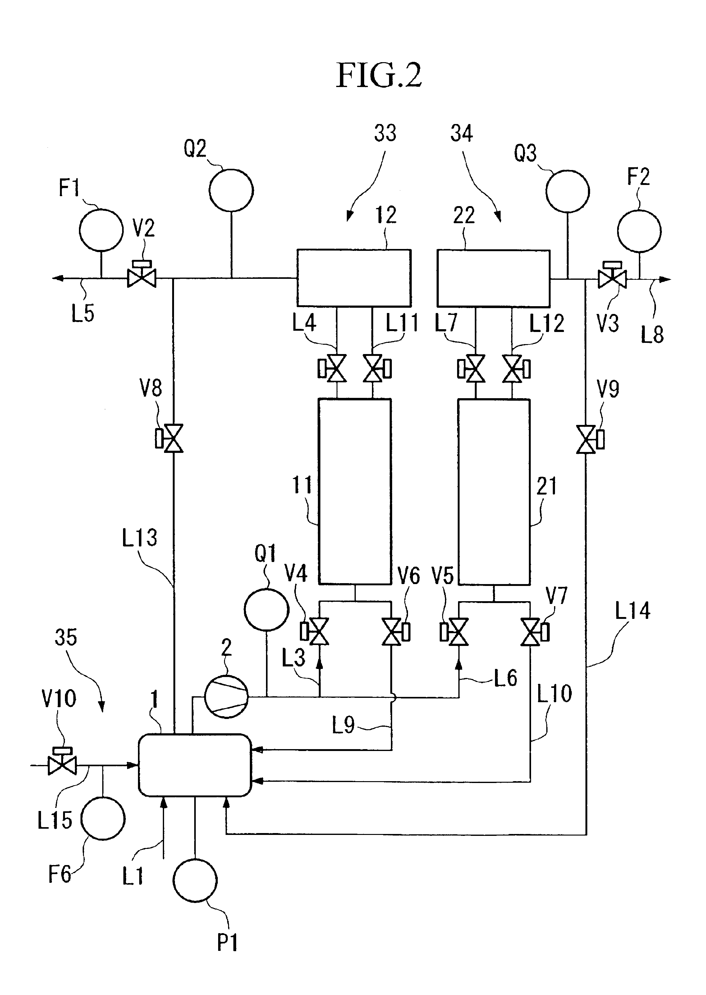
[0099]An experiment to confirm the long-term stability of the apparatus was carried out by using the gas separation apparatus having the structure shown in FIG. 2. The component mechanisms such as the first adsorption column 11 and the second adsorption column 21 and the operating conditions such as the half-cycle time are identical to those of Example 1. In addition, similarly Example 1, a densitometer (concentration detecting part) Q1 that continuously monitors the circulating feed gas concentrations is provided downstream of the compressor 2, a mass flow controller (control valve V2) that adjusts the outflow rate of the nitrogen product is provided on the path L5, and a mechanism that adjusts the outflow rate of the nitrogen product using a PID controller based on the detected value of the densitometer Q1 was provided.

[0100]A krypton tank was installed on the gas supply part 35, and a mass flow controller V10 was installed on the path L15. A pressure detector P1 was installed on ...

example 3

[0105]In the semiconductor manufacturing apparatus that is the object of the present gas separation apparatus, in a plasma process in a krypton atmosphere, a mixed gas consisting of krypton and nitrogen is discharged, and only nitrogen is discharged during the introduction and removal of the substrate. Thus, an experiment that simulates this state was carried out. In the experiment, a gas separation apparatus having a structure identical to that in Example 2 was used.

[0106]In the experiment, first a mixed gas consisting of 50% krypton and 50% nitrogen was supplied for 20 minutes at 2 L / min as feed gas, and then an operation in which nitrogen gas was supplied for 10 minutes at 1 L / min was repeatedly carried out.

[0107]In the 20 minutes during which the mixed gas consisting of 50% krypton and 50% nitrogen was supplied at 2 L / min as feed gas, the nitrogen product was introduced from path L5 at 1.005 L / min and the krypton product was introduced from path L8 at 1 L / min. In addition, in th...


PUM

PropertyMeasurementUnit
pore diameteraaaaaaaaaa
heightaaaaaaaaaa
inner diameteraaaaaaaaaa

Abstract

A gas separation method and apparatus that recovers efficiently principal gas components from a feed gas that includes a plurality of components, and enables supplying the product gases continuously at a stable flow rate and component concentration. A first separation step using a first adsorption column and a second separation step using a second adsorption column are provided, a circulating feed gas, consisting of the recovered exhaust gases discharged in each of the steps and the feed gas, is used as a gas to be separated. The outflow rate and component concentration of a second gas product are maintained constant by controlling the outflow rate of the first gas product.

Description

[0001]This application is the US national phase of international application PCT / JP02 / 12161, filed in English on 21 Nov. 2002, which designated the US. PCT / JP02 / 12161 claims priority to JP Application No.2001-36138l filed 27 Nov. 2001. The entire contents of these applications are incorporated herein by reference.BACKGROUND OF THE INVENTION[0002]1. Field of the Invention[0003]The present invention relates to a method in which a valuable rare gas is separated and recovered from a mixed gas consisting of valuable rare gases such as krypton and xenon, and in particular, to a gas separation method and apparatus in which a valuable rare gas is recovered, and separated at a high purity from a mixed gas that includes mainly a valuable rare gas and nitrogen by using a pressure swing adsorption method, and then circulated and reused.[0004]2. Description of Related Art[0005]In the process of manufacturing semiconductor devices such as semiconductor integrated circuits, liquid crystal panels, ...

Claims


Application Information

Patent Timeline
Patent Type & Authority Patents(United States)
IPC IPC(8): B01D53/047B01D53/04B01D53/053
CPCB01D53/047B01D53/053B01D2253/102B01D2253/108B01D2253/308B01D2256/10B01D2256/18B01D2257/102B01D2257/11B01D2258/0216B01D2259/40007B01D2259/40052B01D2259/40081B01D2259/402
Inventor URAKAMI, TATSUSHINAGASAKA, TOORUKAWAI, MASATONAKAMURA, AKIHIRO
Owner NIPPON SANSO CORP
Why Eureka
Try Eureka