Ion beam lithography system

a lithography system and beam technology, applied in the field of ion beam lithography, can solve the problems of complicated mask technology, low throughput, and inability to meet the requirements of lithography, and achieve the effect of high throughpu

Inactive Publication Date: 2005-08-02
RGT UNIV OF CALIFORNIA
View PDF2 Cites 83 Cited by
  • Summary
  • Abstract
  • Description
  • Claims
  • Application Information

AI Technical Summary

Benefits of technology

[0009]The Maskless Nano-Beam Lithography (MNBL) system of the present invention is a proximity print type of lithography system rather than a projection system. It takes a combined approach of certain aspects of the MMRL and FIB systems, and eliminates the accelerator or reduction column. It employs the same beamlet switching technique as MMRL, i.e. a universal pattern generator. Unlike the FIB system which operates with four or more electrodes, the MNBL syst...

Problems solved by technology

Many of the alternative lithography technologies explored thus far, such as X-ray, extreme-ultraviolet (EUV), electron-beam (e-beam), and ion-beam lithography, have been handicapped by complicated mask technology and/or low throughput.
Focused ion beam (FIB) patterning of films is a well-established technique i...

Method used


Image

  • Ion beam lithography system
  • Ion beam lithography system
  • Ion beam lithography system

Examples


Embodiment Construction

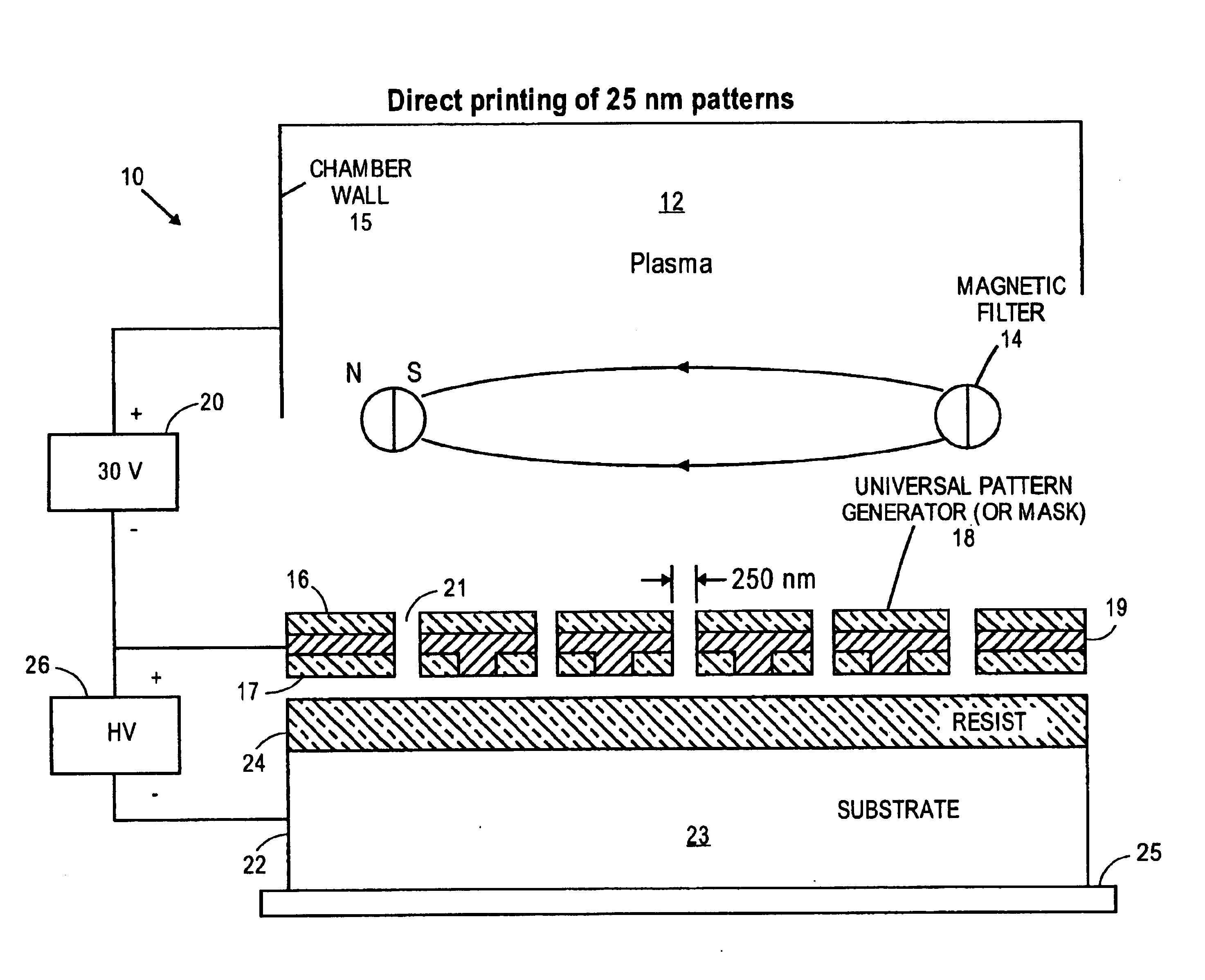
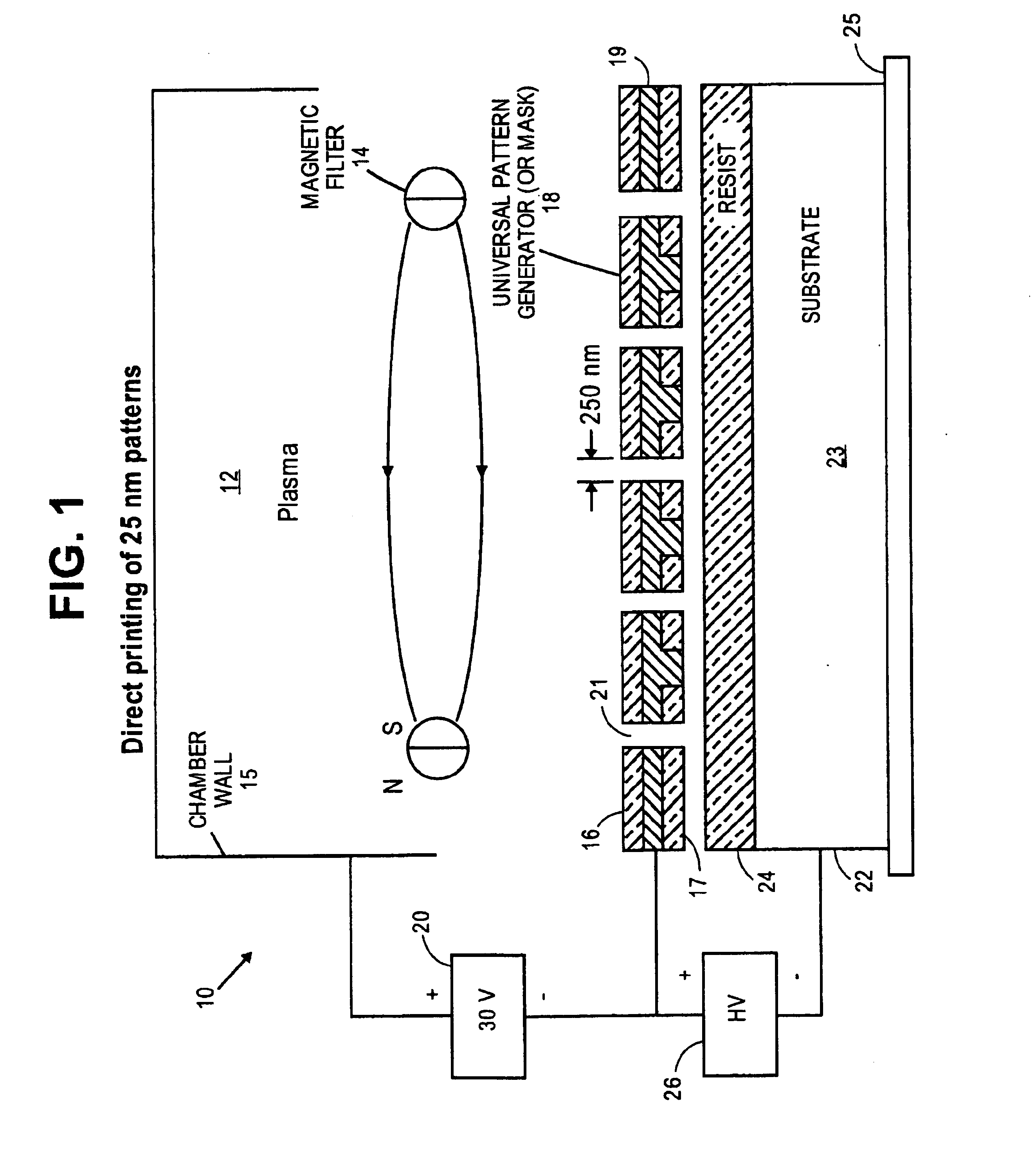
[0027]The principle of the Maskless Nano-Beam Lithography (MNBL) system 10 is illustrated in FIG. 1. A hydrogen (or other) plasma is first generated in a (multicusp) plasma ion source 12. The plasma will diffuse across a permanent-magnet filter 14 which can greatly reduce the axial energy spread of the positive hydrogen ions. The positive ions will accelerate towards the plasma electrode 16 (the first electrode of the pattern generator 18) with an energy of ˜25 eV. A low voltage, e.g. about 30V, power supply 20 connected between chamber wall 15 and pattern generator 18 provides a bias voltage to accelerate the ions towards electrode 16. Pattern generator 18 is formed of a pair of electrodes 16, 17 separated by an insulator 19 and a plurality of apertures 21 are formed in pattern generator 18. As the ions emerge from the apertures 21, the ion beam made up of the beamlets which pass through the apertures 21 will be further accelerated to the wafer target 22 which is formed of a wafer ...


PUM


Abstract

A maskless plasma-formed ion beam lithography tool provides for patterning of sub-50 nm features on large area flat or curved substrate surfaces. The system is very compact and does not require an accelerator column and electrostatic beam scanning components. The patterns are formed by switching beamlets on or off from a two electrode blanking system with the substrate being scanned mechanically in one dimension. This arrangement can provide a maskless nano-beam lithography tool for economic and high throughput processing.

Description

RELATED APPLICATIONS[0001]This application claims priority of Provisional Application Ser. No. 60 / 149,512 filed Aug. 17, 1999.GOVERNMENT RIGHTS[0002]The U.S. Government has rights in this invention pursuant to Contract No. DE-AC03-76SF00098 between the U.S. Department of Energy and the University of California.BACKGROUND OF THE INVENTION[0003]The invention relates generally to ion beam lithography and more particularly to proximity print type ion beam lithography capable of producing sub-50 nm feature size.[0004]If microelectronics manufacturing is to continue its progress toward ever higher levels of performance and integration as well as lower cost per function, alternative lithographic techniques will be needed in order to resolve features of 50 nm and smaller. These techniques must offer high process throughput and reasonable cost per wafer. Many of the alternative lithography technologies explored thus far, such as X-ray, extreme-ultraviolet (EUV), electron-beam (e-beam), and i...

Claims


Application Information

Patent Timeline
IPC IPC(8): H01J37/30H01J37/302H01J37/317
CPCB82Y10/00B82Y40/00H01J37/045H01J37/08H01J37/3174H01J2237/0435H01J2237/1205H01J2237/21H01J2237/3175H01J2237/31755H01J2237/31774H01J2237/31788
Inventor LEUNG, KA-NGO
Owner RGT UNIV OF CALIFORNIA
Why Eureka
Try Eureka