Closed-loop, rapid manufacturing of three-dimensional components using direct metal deposition

a three-dimensional component, closed-loop technology, applied in the direction of manufacturing tools, soldering devices, instruments, etc., can solve the problems of not timely, not saving the product, and the finished product is not used or operated in time, so as to improve lead-time and design flexibility, and improve throughput

Inactive Publication Date: 2005-08-02
DM3D TECH
View PDF16 Cites 78 Cited by
  • Summary
  • Abstract
  • Description
  • Claims
  • Application Information

AI Technical Summary

Benefits of technology

[0012]To enhance throughput, multiple nozzles are preferably employed to independently control speed and deposit dimension in a closed-l

Problems solved by technology

Most existing techniques, however, are based on open-loop processes requiring either considerable amount of periodic machining or final machining for close dimensional tolerances.
Residual stresses, for example, may accumulate and lead to di

Method used


Image

  • Closed-loop, rapid manufacturing of three-dimensional components using direct metal deposition
  • Closed-loop, rapid manufacturing of three-dimensional components using direct metal deposition
  • Closed-loop, rapid manufacturing of three-dimensional components using direct metal deposition

Examples


Embodiment Construction

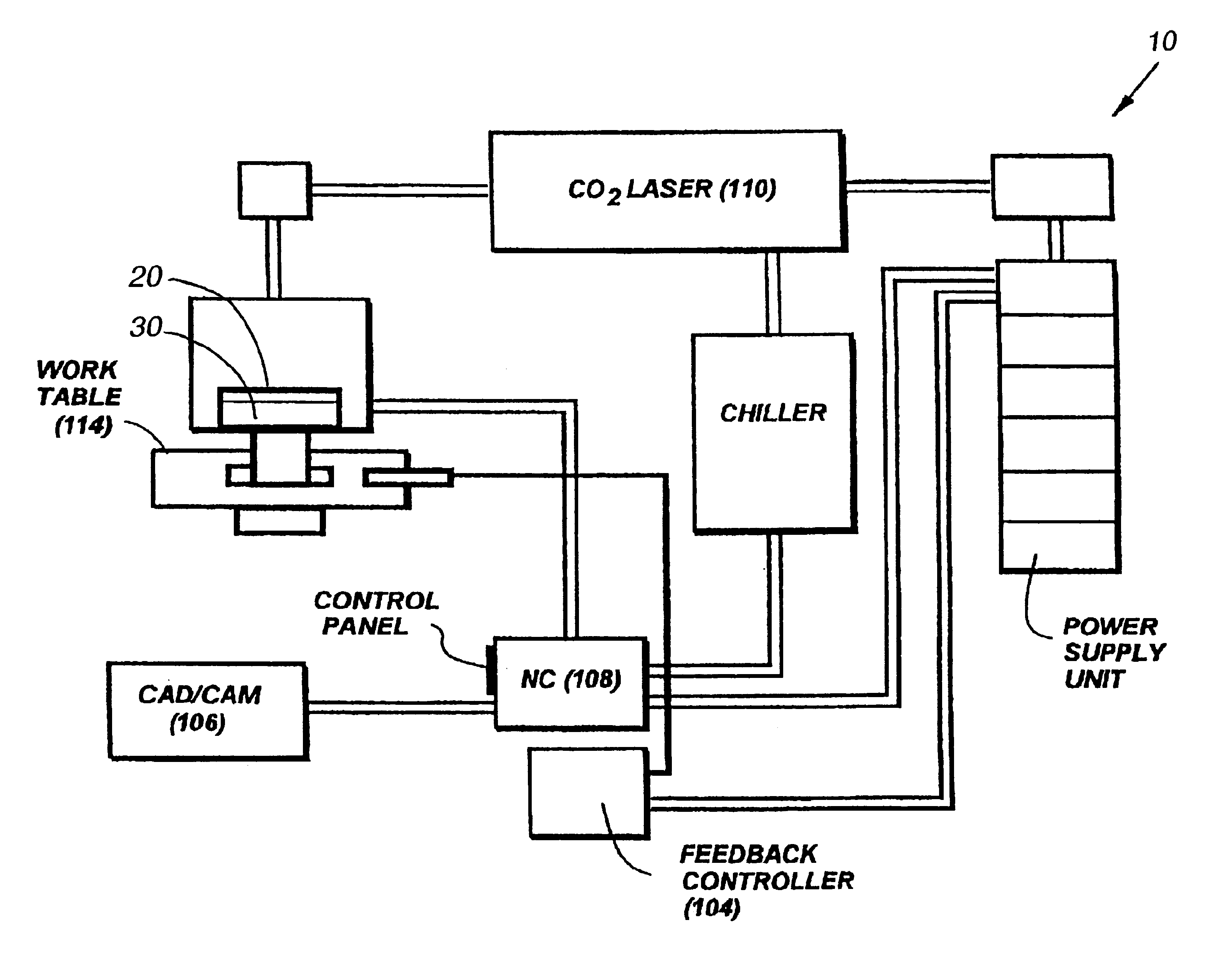
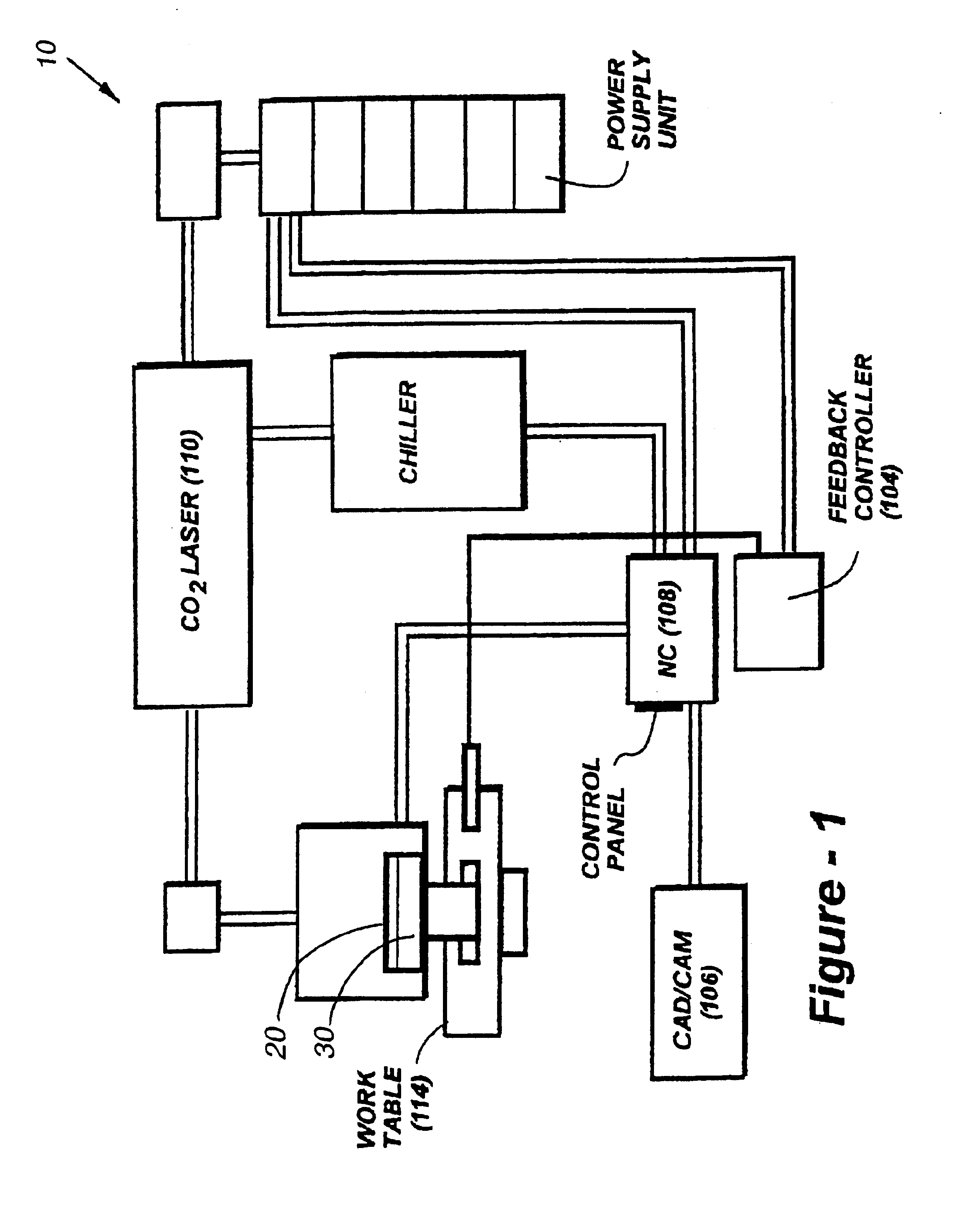
[0025]By way of a review, FIG. 1 illustrates a laser-aided, computer controlled direct material deposition (DMD) system in schematic form. The system 10 applies layers of material 20 on a substrate 30 to fabricate an object or cladding. As discussed above, the system is preferably equipped with feedback monitoring to control of the dimensions and overall geometry of the fabricated article. The geometry of the article is provided by a computer-aided design (CAD) system.

[0026]The deposition tool path is generated by a computer-aided manufacturing (CAM) system for CNC machining with post-processing software for deposition, instead of software for removal as in conventional CNC machining. CAM software interfaces with a feedback controller 104. These details of the laser-aided, computer controlled direct material deposition system can be found in U.S. Pat. No. 6,122,564, and are therefore not all explicitly shown in FIG. 1. The factors that affect the dimensions of material deposition in...


PUM

PropertyMeasurementUnit
Temperatureaaaaaaaaaa
Thicknessaaaaaaaaaa
Poweraaaaaaaaaa

Abstract

Multiple criteria are monitored and controlled to enhance the success of direct-metal deposition, including greater control over factors such as deposit layer height/thickness, sub-harmonic vibration, contour path shape, powder mass flow, and deposition speed, and stress accumulation. Sensors are used to monitor some or all of the following parameters during the deposition process: deposit height, width, temperature, and residual stress. A predetermined limit with respect to the yield strength of the material is preferably set. If the stress exceeds that limit sensors will automatically introduce one or more remedial measures, the priority of which is established using a look-up table generated in accordance with prior experimental knowledge. To control temperature induced distortion and stress, an infrared temperature detector may be used in conjunction with a controller to reduce temperature, increase speed and decreased power for purpose of stress management.

Description

REFERENCE TO RELATED APPLICATIONS[0001]This application claims priority of U.S. provisional patent application Ser. Nos. 60 / 156,250, filed Sep. 27, 1999; 60 / 204,303, filed May 15, 2000; 60 / 208,599, filed Jun. 1, 2000 and is a continuation-in-part of U.S. patent application Ser. Nos. 09 / 526,631, filed Mar. 16, 2000; Ser. No. 09 / 570,986, filed May 15, 2000, now U.S. Pat. No. 6,410,105; and Ser. No. 09 / 608,874, filed Jun. 30, 2000 now abandoned, which is a continuation-in-part of U.S. patent application Ser. No. 09 / 107,912, filed Jun. 30, 1998, now U.S. Pat. No. 6,122,564, the entire contents of each application being incorporated herein by reference.FIELD OF THE INVENTION[0002]This invention relates generally to the layered fabrication of three-dimensional components and, in particular, to a closed-loop system and method wherein a plurality of parameters may be monitored to optimize a direct metal deposition process.BACKGROUND OF THE INVENTION[0003]Fabrication of three-dimensional met...

Claims


Application Information

Patent Timeline
IPC IPC(8): B23K26/00B23K26/02B23K26/34B23K26/03C23C4/12C23C24/10C23C24/00
CPCB23K26/032B23K26/034B23K26/34B23K35/0244C23C24/10B23K26/3206C23C4/12B23K26/32B22F2999/00B23K2103/50B33Y40/00Y02P10/25B22F10/64B22F10/368B22F10/25B22F10/85B22F12/90B22F3/1017
Inventor MAZUMDER, JYOTIKELLY, JOSEPH K.
Owner DM3D TECH
Why Eureka
Try Eureka