
Method for measuring fluid chemistry in drilling and production operations

a technology of fluid chemistry and production operations, applied in the field of measuring and analysing drilling, drilling, drilling completion, productionand formation fluids, can solve the problems of not entirely satisfactory analytical tools, simple, yet relatively time-consuming analytical tests, and large variation in applications, so as to achieve minimal human and environmental impacts, minimal sample size, and minimal turn-around time

Inactive Publication Date: 2005-08-02
SHELL OIL CO
View PDF30 Cites 63 Cited by
  • Summary
  • Abstract
  • Description
  • Claims
  • Application Information

AI Technical Summary

Benefits of technology

The present invention is a method for automated chemical measurements on drilling, drill-in, completion, and production fluids using microfluidics that require only small quantities of fluid and reagents to perform the tests. This allows for minimal turn-around time, minimal sample size, and minimal human and environmental impacts of chemicals due to the use of low effective concentrations. The method can be incorporated into a benchtop tool, an in-line tool, or a down-hole chemical analyzer. The method uses microfluidic devices that have pre-defined channels and wells for holding the sample fluid, and the transport of the fluid inside the channels is accomplished by using electro-kinetic forces or pressure gradients. The method measures the concentration of a sample by comparing it to a known standard fluid, and the results can be used to adjust the drilling, drill-in, completion, or production operation. The method can also identify imbalances in the fluid's chemistries and adjust the concentration of certain chemicals to mitigate potential issues.

Problems solved by technology

Typically, these tests are one or two daily measurements of the fluid with simplistic, yet relatively time-consuming analytical tests.
Considering the complexity of the fluid systems, the high cost of drilling and completing a well, and the danger of production losses, such tests are not entirely satisfactory analytical tools.
The measurement principles for chemical sensors and chemical sensing devices for liquids and gases are in some cases similar, but the applications are generally very different due to the great differences in complexity and variability of the target species.
Important points to note are that the method relies on a calibration set of well-characterized materials, which may or may not correspond to materials in field use, and has very limited accuracy for the mineralogy estimates, with no indication of the accuracy of the other estimates.
In addition, while the method is claimed to require no sample preparation, the importance of scattering limits the particle size distribution in the samples to be analyzed.
Thus, it is asserted that adaptation to an on-line application would be limited.
Unfortunately, total reflectance is well known to those knowledgeable in the art to be notoriously dependent on particle size in turbid fluids and to be difficult to quantify in the laboratory.
Thus, a subtraction operation applied to two profiles that are not quantitative is highly unlikely to produce useful results.
Thus, this approach is highly unlikely to be useful with synthetic- / oil-based muds, which have hydrocarbons as the external phase.
A key element of the sol / gel approach is that once a unit has reacted to produce a species detectable by optical spectroscopy, it cannot be re-used.
Thus, the method cannot be used to evaluate mud chemistry downhole on a routine basis.
It is important to note that these systems have only been applied to explosives, and that single-use units are not appropriate for flowing systems in which repeated measurements must be made.
While no specific application or type of application was described for this tool, the approach is single-use and is not feasible for use in a flowing fluid.
Again, these single use systems would be unfit for flowing systems in which repeated measurements must be made.
Other research abstracts from CPAC propose: 1) vapochromic detection and identification of volatile organic compounds applicable to a variety of simple compounds in a single-use approach; 2) surface plasmon resonance sensors, with proposed applications for bioanalytes; 3) Raman spectroscopy for process monitoring and materials characterization (Historically this approach has been limited to white solids or colorless solutions since the intense power of the laser is absorbed by darker-colored materials, resulting in rapid temperature increases.
Application to drilling fluids, for example, would be limited on this account.
And application to, for example, drilling fluids would be limited due to the complexity of the spectra and the insensitivity to metal ions); 4) Process liquid chromatography and sampling on a micro-scale are under development; and 5) The concept of a “Lab-on-a-Valve” for the monitoring of fermentation.

Method used


Image

  • Method for measuring fluid chemistry in drilling and production operations
  • Method for measuring fluid chemistry in drilling and production operations
  • Method for measuring fluid chemistry in drilling and production operations

Examples


example 1

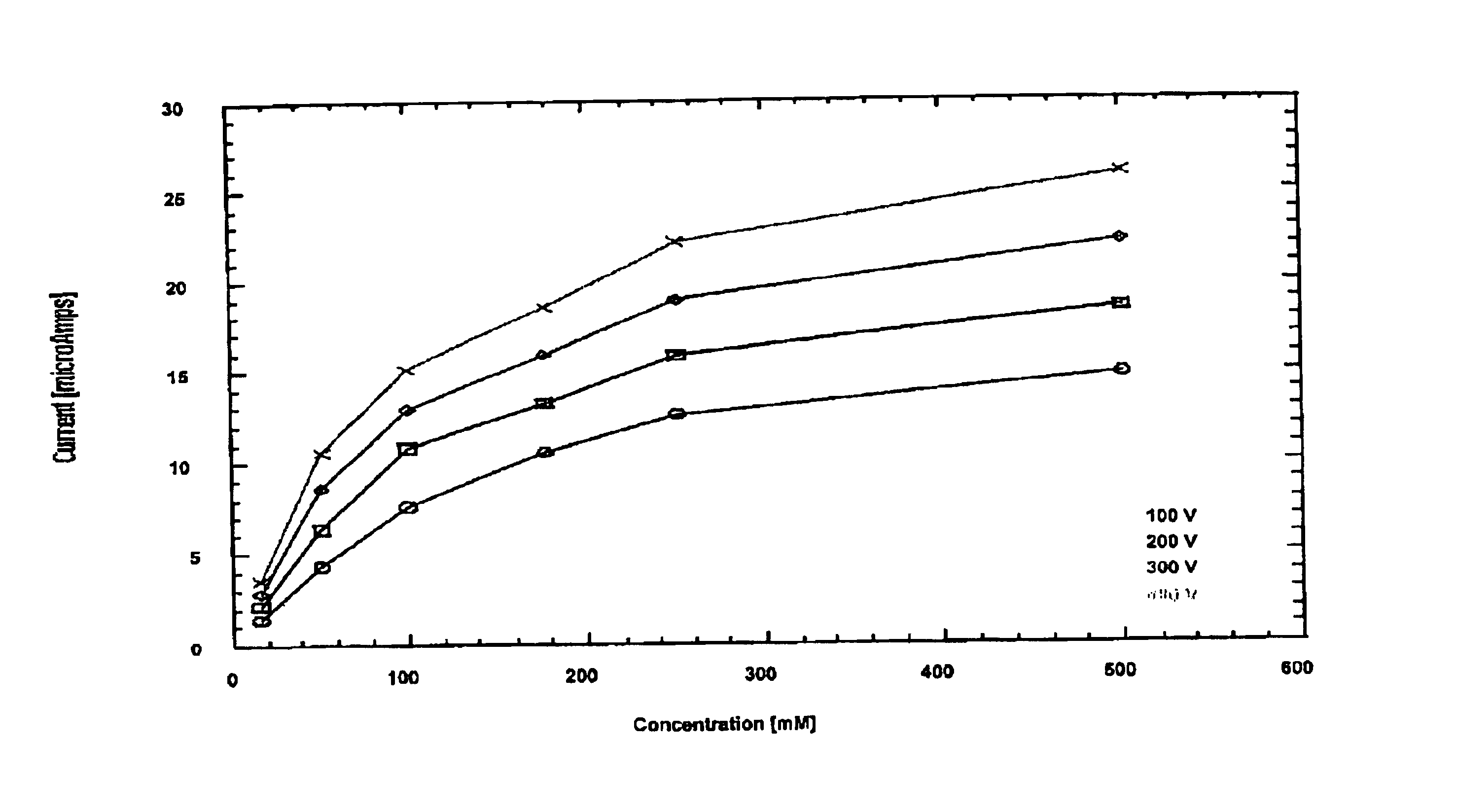
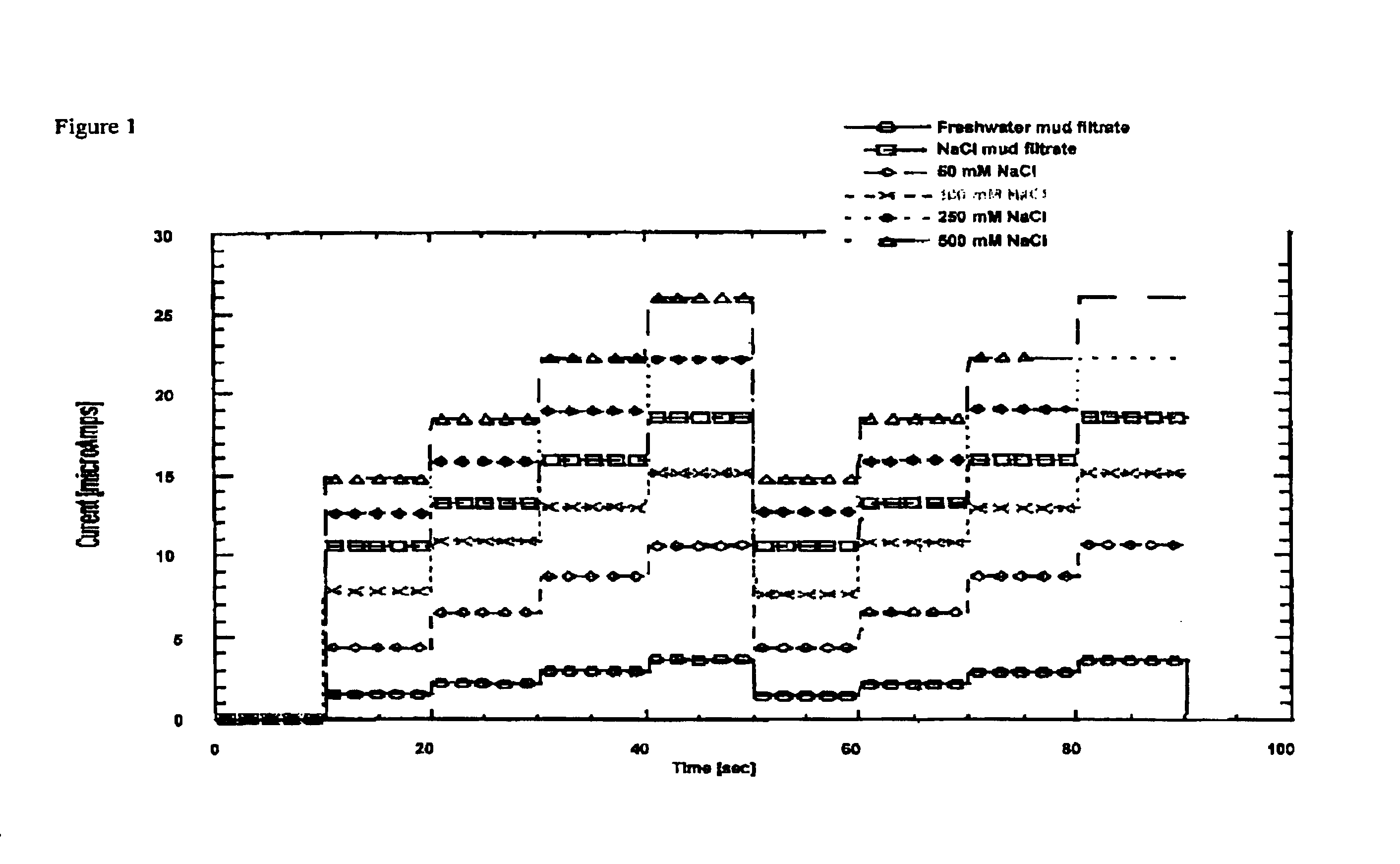
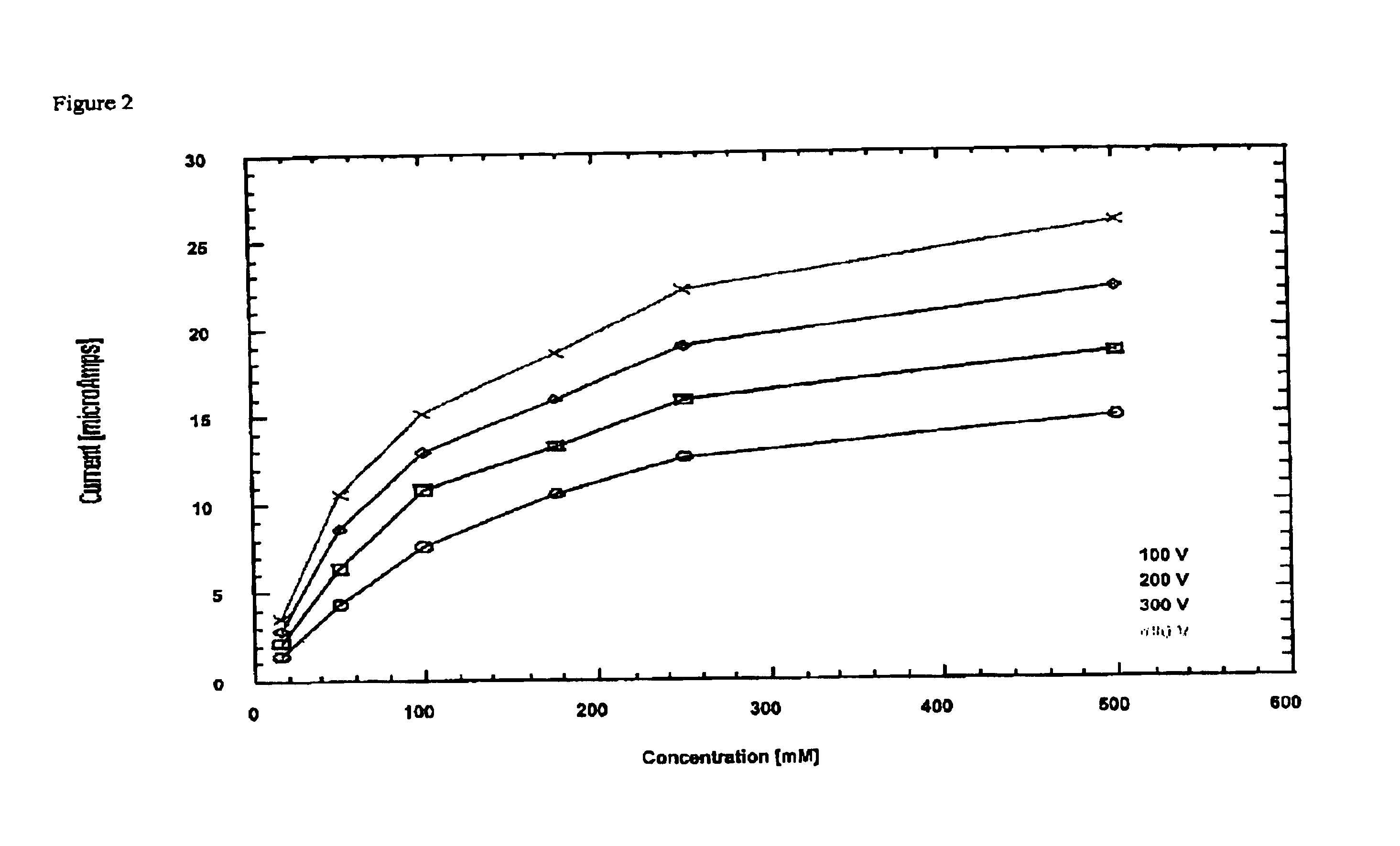
[0088]In Example 1, resistivity or conductance of freshwater / PHPA drilling fluid filtrate and of sodium chloride / PHPA was measured. The fluid was 2M NaCl in a buffer, 10 mM Tris pH 7.5. The stock solution was diluted with water to working solutions of 50 mM, 100 mM, 250 mM, and 500 mM. The freshwater / PHPA filtrate was used undiluted, while the saltwater / PHPA filtrate was diluted 1:10.

[0089]The microfluidic device that was employed for measuring the resisitvity used at least three wells to hold the fluids: sample fluid, standard fluid and waste well. The wells were connected to each other and all to the waste well.

[0090]Before use the chip was cleaned with a 1 Normal NaOH solution, and flushed with buffer before introducing the sample and the standard fluids. A voltage of 100V, 200V, 300V and 400 V was applied across the channels and the responding current was measured, thus calculation of the resistance was possible using aforementioned Equation 1. A software program was employed to...

example 2

[0095]In Example 2 chloride concentration was measured. The measurement principle in this experiment is fluorescence. The microfluidic device that was employed for measuring the chloride concentration used at least five wells to hold the fluids: sample fluid, standard fluid, buffer, dye and waste well. The wells were connected to each other and all to the waste well. The standard stock was 100 mM NaCl in a buffer, 10 mM borate buffer pH 9.2. The working solution was 100 mM diluted with 10 mM borate buffer pH 9.2. The dye was 40 μM Lucigenin in 10 mM borate buffer pH 9.2. The samples were freshwater and 10% NaCl drilling fluid. The freshwater sample was used undiluted, while the NaCl-containing drilling fluid filtrate was diluted 1:17. The protocol is as follows:[0096](1) Cleaning the chip with 1 Normal NaOH solution and flushing the chip with HPLC grade water.[0097](2) Then the water was removed from the wells and the wells loaded with the sample, standard, buffer, and dye. A softwa...

example 3

[0101]The third example shows the measurement of calcium concentration in a microfluidic chip. The measurement principle, again, is fluorescence, but here a fluorescent dye, fluo-5N (U.S. Pat. No. 5,049,673) is used. This dye increases its intensity upon addition of calcium. Note a similar response can be achieved using Oregon Green (BAPTA-2 octapotassium salt, patented and available from Molecular Probes). The sample preparation is as follows: five micromolar of Fluo-5N is diluted in a MOPS buffer. The starting concentration of calcium in the standard solution is 60 mM. The result is shown in FIG. 5. The first two steps of the stair steps are the buffer-base line and the 100% dye line the subsequent steps are of 1:16; 1:8 and 1:4 addition of the 60 mM calcium-buffer solution. The second stair step, using buffer solution and a 60 mM calcium solution (representing the test fluid) in separate wells is an identical stair case to the first staircase.


PUM

PropertyMeasurementUnit
wavelengthaaaaaaaaaa
excitation wavelengthsaaaaaaaaaa

Abstract

A method for chemical analysis of fluids utilized in hydrocarbon exploration and production in which microfluidic systems designed to react to specific characteristics of a fluid are introduced into fluid samples or during operations. The microfluidic systems are then recovered and subjected to analysis to permit one to measure the desired characteristics.

Description

[0001]This application claims the benefit of U.S. Provisional Application No. 60 / 404,899 filed Aug. 21, 2002, the entire disclosure of which is hereby incorporated by referenceFIELD OF THE INVENTION[0002]This invention relates to the measurement and analysis of drilling-, drill-in, completion-, production- and formation fluids on the well site or in a remote laboratory. More particularly it relates to microfluidic (i.e. micro-electronic machines type or MEMS) technology, measuring drilling-, drill-in, completion-, formation and production fluids in real-time, on-site or remote, faster, more reliably and more economically, with better reproducibility of results. Examples of fluid properties that can be measured with the proposed method include, for example, measurements of ion concentration in the fluids such as chloride concentration, water hardness (Ca2+, Mg2+), bromide ion concentration, heavy metals such as Zn, Ba, and Cd, shale reactivities, zeta potential, enzymes, and biopolym...

Claims


Application Information

Patent Timeline
Patent Type & Authority Patents(United States)
IPC IPC(8): G01N33/28G01N33/26G16Z99/00B01L3/00E21B1/00E21B47/00E21B49/08G01N1/10G01N35/00
CPCG01N33/2823B01L3/5027G16Z99/00
Inventor MCNEIL, III, ROBERT IRVINGZEILINGER, SABINE CLAUDIANICHOLSON, JAMES WILLIAM
Owner SHELL OIL CO
Learn More