
Extensible, visible light-transmissive and infrared-reflective film and methods of making and using the film

a visible light-transmissive and infrared-reflective film technology, applied in the field of infrared-reflective films and optical articles, can solve the problems of nip roll lamination typically limited, optical defect in the safety glazing, and the functional layer b>12/b> does not always conform adequately to complex curves, etc., to improve outward visibility and enhance vehicle aerodynamics.

Inactive Publication Date: 2005-08-16
3M INNOVATIVE PROPERTIES CO
View PDF98 Cites 87 Cited by
  • Summary
  • Abstract
  • Description
  • Claims
  • Application Information

AI Technical Summary

Benefits of technology

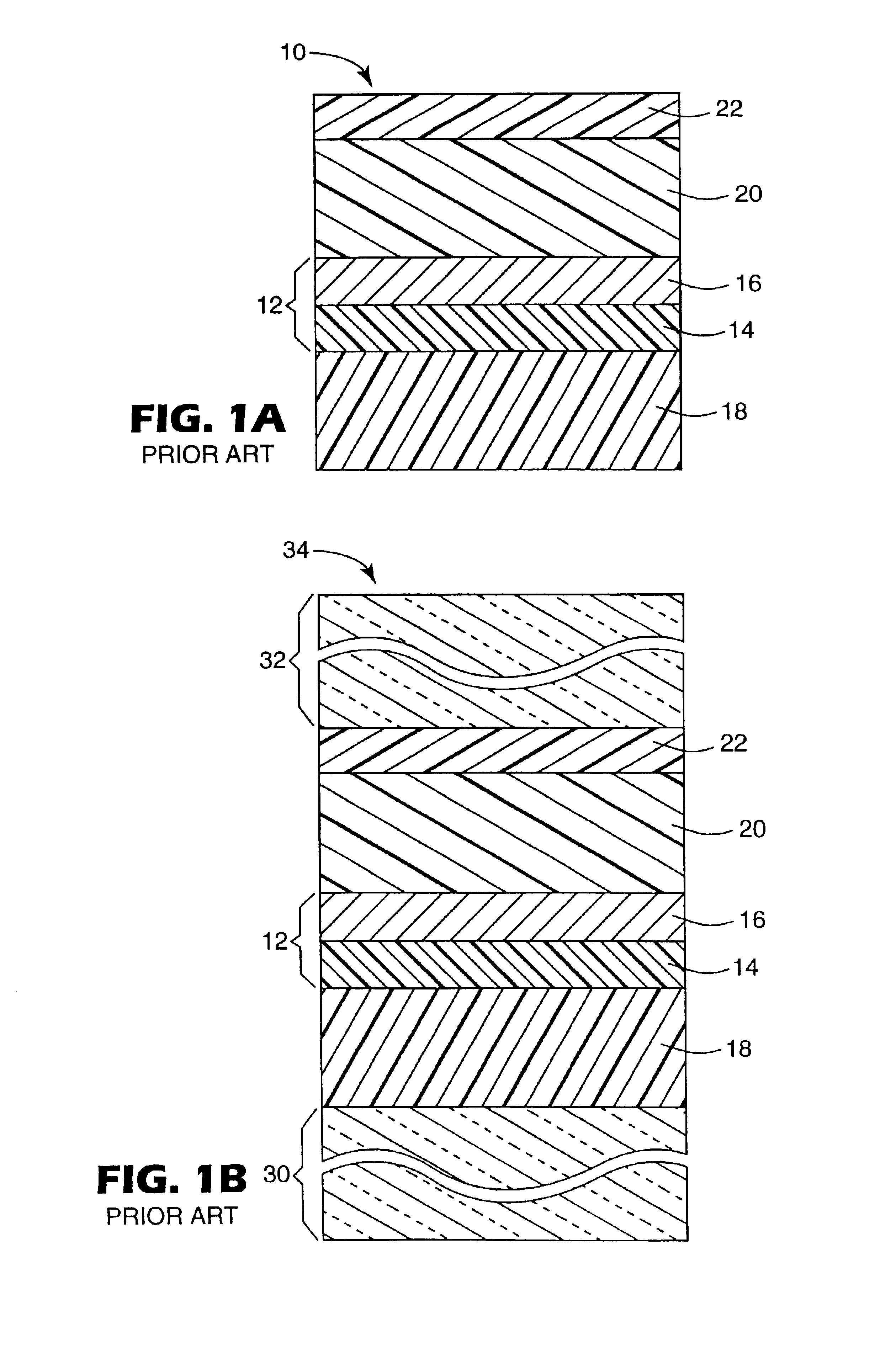
[0007]To enhance vehicle aerodynamics and improve outward visibility, many vehicular window shapes are not planar, and increasingly include severe angles and complex curves. When the pre-laminate 10 is placed between complex curved glass sheets, the functional layer 12 does not always conform adequately to complex curves, especially when the glass sheets are large or when the nip roll method is employed. Wrinkles, folds or pleats can form in the functional layer 12. If functional layer 12 is metallized, cracks can form in the metallized layer 16 during nip rolling, creating an optical defect in the safety glazing. At present, nip roll lamination typically is limited to small metallized laminates having no curvature or only modest one-dimensional curvature.
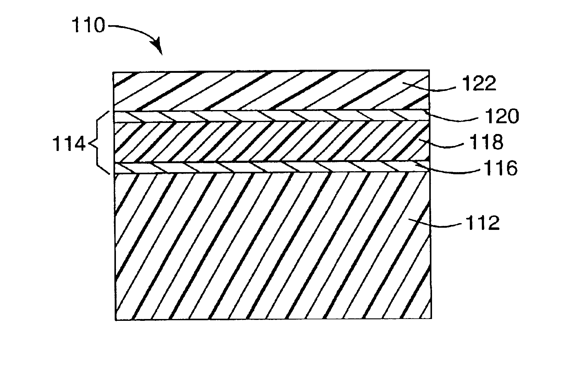
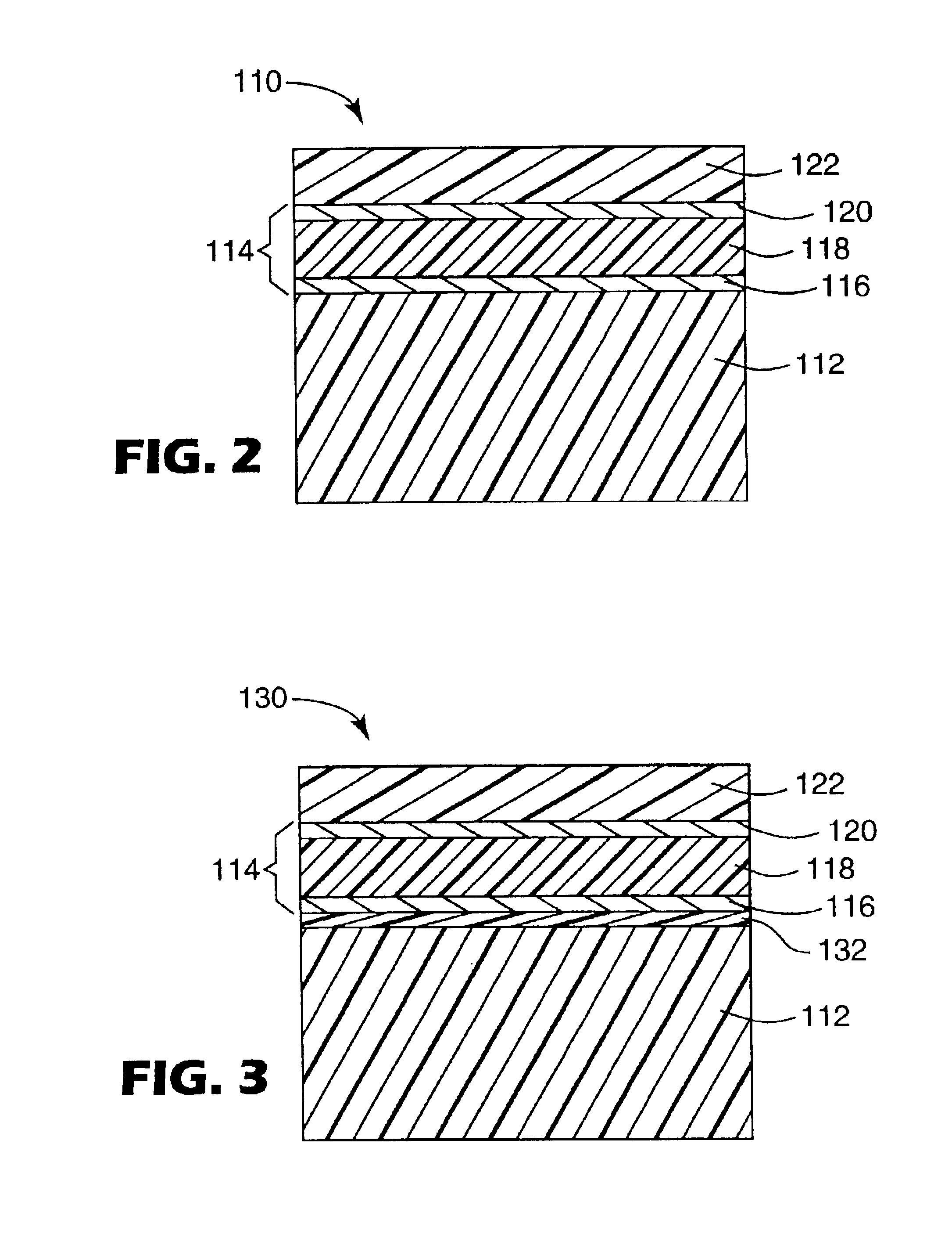
[0009]We have found that by forming the dielectric layer from a polymer that is crosslinked, we can successfully laminate functional layers containing Fabry-Perot stacks into non-planar glazing. The results appear to be much better than those obtained when the dielectric layer is formed entirely from an inorganic material or entirely from an uncrosslinked organic material. We have also found that a further improvement can be obtained by modifying an interface between the thin metal layer or layers and adjacent layers within the film to enhance interlayer adhesion.

Problems solved by technology

When the pre-laminate 10 is placed between complex curved glass sheets, the functional layer 12 does not always conform adequately to complex curves, especially when the glass sheets are large or when the nip roll method is employed.
If functional layer 12 is metallized, cracks can form in the metallized layer 16 during nip rolling, creating an optical defect in the safety glazing.
At present, nip roll lamination typically is limited to small metallized laminates having no curvature or only modest one-dimensional curvature.
However, these attempts have met with only limited success.
Fabrication of non-planar glazing is particularly difficult.
We believe these difficulties may be due in part to the fragility of one or more of the stack layers, to the tendency of the metal layers to corrode, or to localized changes in the distance between the metal layers caused by the stretching, heating and cooling that take place during lamination, autoclaving and subsequent use of the glazing.
We believe that these adjuvants can migrate into an infrared-rejecting functional layer and cause corrosion, swelling or other effects that can lead to localized changes in to distance between the metal layers.

Method used


Image

  • Extensible, visible light-transmissive and infrared-reflective film and methods of making and using the film
  • Extensible, visible light-transmissive and infrared-reflective film and methods of making and using the film
  • Extensible, visible light-transmissive and infrared-reflective film and methods of making and using the film

Examples


example 1

[0086](Layer 1) An approximately 300 meter long roll of 0.05 mm thick by 508 mm wide PET support (453 MELINEX™, DuPont Teijin Films) was loaded into a roll to roll vacuum chamber like that shown in FIG. 8. The pressure in the vacuum chamber was reduced to 3×10⁻⁴ torr. The support was simultaneously plasma pretreated and acrylate coated at a web speed of 36.6 m / min. The plasma pretreatment utilized a chrome target and an unbalanced dc magnetron operated at 1500 watts power (429 volts and 3.5 amps) under a nitrogen atmosphere with a nitrogen gas flow of 70 sccm. The acrylate coating employed a 50:50 mixture of IRR214 acrylate (UCB Chemicals) and lauryl acrylate that had been degassed for 1 hour by placing a container of the liquid monomer mixture into a bell jar and reducing pressure to approximately 1 millitorr. The degassed monomer was pumped at a flow rate of 2.35 ml / min through an ultrasonic atomizer into a vaporization chamber maintained at 274° C. Using a drum temperature of −18...

example 2

[0092]Using the method of Example 1, a PET support was covered with a five layer acrylate / Ag / acrylate / Ag / acrylate optical stack, but using plasma pretreatment on both the top and bottom of the metal layers. The individual layer differences were as follows:

[0093](Layer 1) The support plasma pretreatment was as before but at 1000 watts power (402 volts and 2.5 amps) and a nitrogen gas flow of 102 sccm. The monomer flow rate was 2.45 ml / min and the vaporization chamber temperature was 276° C. The monomer vapor was condensed onto the moving web using a −21° C. drum temperature. The electron beam filament was operated at 8.0 kV and 6.5 milliamps.

[0094](Layer 2) The plasma pretreatment was at 1000 watts power (309 volts and 3.34 amps) and a nitrogen gas flow of 90 sccm. The silver was sputtered at 570 volts and 17.88 amps, a drum temperature of 21° C. and an argon gas flow of 93.2 sccm.

[0095](Layer 3) The silver surface was plasma pretreated prior to deposition of the spacing layer. The p...

examples 3-5

[0099]Using the method of Example 2, 5 layer infrared-rejecting acrylate / Ag / acrylate / Ag / acrylate optical stacks were formed on a PET support. The resulting films were evaluated for appearance, transmission (Trans-Luminous Y (Tvis)), reflection (Refl-Luminous Y), solar heat gain coefficient, shading coefficient and corrosion resistance. The processing conditions and evaluation results are set out below in Table 1, along with results for the films of Examples 1 and 2.

[0100]

TABLE 1Ex.1Ex.2Ex.3Ex.4Ex.5Layer 1Deposited materialMonomersMonomersMonomersMonomersMonomersLine speed (m / min)36.636.636.636.636.6Plasma (Watts)15001000150010001000Drum temp(° C.)−18−21−18−21−19Monomer feed (ml / min)2.352.452.352.452.45Layer 2Deposited materialAgAgAgAgAgLine speed (m / min)36.636.630.538.136.6Plasma (Watts)15001000150010001000Drum temp (° C.)2522252219Sputter power (KW)1010101010Layer 3Deposited materialMonomersMonomersMonomersMonomersMonomersLine speed (m / min)36.636.636.636.636.6Plasma (Watts)01000010...


PUM

PropertyMeasurementUnit
Temperatureaaaaaaaaaa

Abstract

A film contains first and second metal or metal alloy layers separated by a crosslinked polymeric spacing layer whose thicknesses are such that the film is extensible visible light-transmissive and infrared reflective. The film can be joined or laminated into glazing (especially non-planar vehicular safety glazing) with reduced likelihood that the metal or metal alloy layers will be damaged or distorted.

Description

FIELD OF THE INVENTION[0001]This invention relates to infrared reflecting films and optical articles made therefrom.BACKGROUND[0002]Glazing materials sometimes include one or more functional layers engineered to enhance the performance of the glazing. One important functional layer reduces transmission of infrared radiation. Infrared-rejecting functional layers are typically made of partially transparent metallized or dyed polymer film constructions that reflect or absorb unwanted solar radiation. References describing such functional layers include U.S. Pat. Nos. 4,590,118, 4,639,069 and 4,799,745.[0003]Infrared-rejecting functional layers are of particular interest in vehicular safety glazing. Conventional vehicular safety glazing is a laminate of two rigid layers, typically glass, and an anti-lacerative mechanical energy-absorbing interlayer, typically plasticized polyvinyl butyral (“PVB”). The glazing is prepared by placing the PVB layer between the glass layers, eliminating air...

Claims


Application Information

Patent Timeline
IPC IPC(8): G02B5/28G02B5/20B32B15/08
CPCB32B17/10B32B17/10036B32B17/10174B32B17/10761B32B17/10862G02B5/282B32B17/10871G02B5/208B32B2367/00Y10T428/31692Y10T428/31678Y10T428/31699B32B17/10005B32B2605/006
Inventor FLEMING, ROBERT JAMESBRIGHT, CLARK IVANLYONS, CHRISTOPHER STEWART
Owner 3M INNOVATIVE PROPERTIES CO
Learn More