Apparatus for treating the surface with neutral particle beams

a technology of neutral particle beams and apparatuses, which is applied in the direction of plasma technique, coating, nuclear engineering, etc., can solve the problems of damage to the device formed on the target, super-finely treated targets cannot be obtained, and formation of damaged layers, etc., and achieves a wide effective cross section and high flux of hyperthermal neutral particle beams.

a technology of neutral particle beams and apparatuses, which is applied in the direction of plasma technique, coating, nuclear engineering, etc., can solve the problems of damage to the device formed on the target, super-finely treated targets cannot be obtained, and formation of damaged layers, etc., and achieves a wide effective cross section and high flux of hyperthermal neutral particle beams.

US6935269B2Inactive Publication Date: 2005-08-30SEM TECH CO LTD +1

Image

  • Apparatus for treating the surface with neutral particle beams
  • Apparatus for treating the surface with neutral particle beams
  • Apparatus for treating the surface with neutral particle beams

Examples


Embodiment Construction

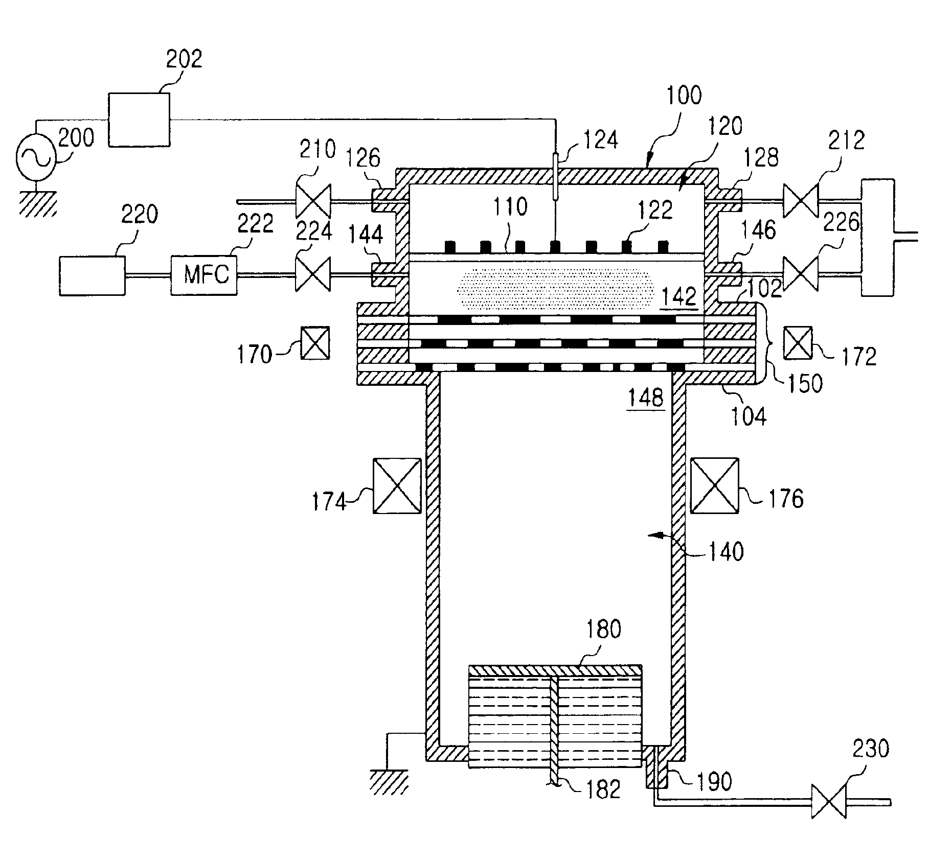
[0011]To achieve the task stated above, there is provided an apparatus comprising a high frequency electric power introducing part, a plasma generating part, a neutral particle beam generating part and a treating part. More specifically, the apparatus comprises an antenna container which comprises antenna connected to high frequency electric power supply through which high frequency electric power supplies, a plasma generating part which transfers gases from a gas injector into plasmas with the supplied power, the neutral particle beam generating part which reverts the obtained plasmas to neutral particle beams via a collision thereof with metal plates, and the treating part which treats the surface of a target with the neutral particle beams.

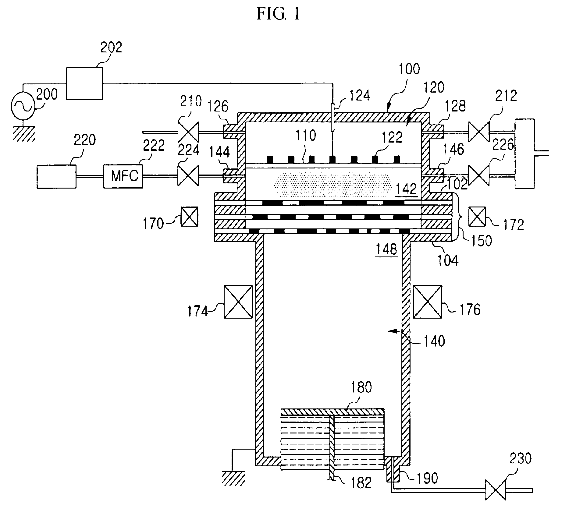
[0012]The antenna container according to the present invention comprises an antenna supporting panel into which looped or spiral high frequency antennas are installed. The antennas are connected to a high frequency power supply through a feedin...


PUM

PropertyMeasurementUnit
Pressureaaaaaaaaaa
Diameteraaaaaaaaaa
Sizeaaaaaaaaaa

Abstract

The present invention relates to an apparatus for treating the surface with neutral particle beams comprising an antenna container, a plasma generating part, a neutral particle beam generating part and a treating part, wherein the antenna container comprises antennas connected to high frequency electric power supply through which high frequency electric power supplies, the plasma generating part transfers gases from a gas injector into plasmas with the supplied power, the neutral particle beam generating part reverts the obtained plasmas to neutral particle beams via the collision thereof with metal plates, and the treating part treats the surface of a target with the neutral particle beams.

Description

TECHNICAL FIELD OF THE INVENTION[0001]The present invention relates to a semiconductor manufacturing equipment, more specifically, to a semiconductor manufacturing equipment which treats with neutral particle beams the surface of a target such as a wafer or a liquid crystal panel used in the manufacturing process of a semiconductor or a liquid crystal panel.BACKGROUND OF THE INVENTION[0002]Plasma, which is generated inside a vacuum chamber, is being widely used in unit processes such as dry etching, physical or chemical vapor deposition, sensitizer cleaning, or other surface treatments. In order to generate plasma, there are installed antennas on the upper inside or outside of the plasma chamber and a target holder on the lower portion of the chamber. By supplying the high frequency electric power into upper inside space of the chamber through the antennas, a processing gas inside the chamber is dissociated and the plasma is generated by glow discharge. When the bias voltage applies...

Claims


Application Information

Patent Timeline
30 Aug 2005
Publication
US6935269B2
IPC
H01J37/32; G21K5/04; H01L21/3065; G21K1/00; H01L21/31; H05H1/46; H05H3/06
CPC
H01J37/32357; H01L21/302
Inventors
LEE, BONG-JU; YOO, SUK-JAE