Method and system for calibrating the scan amplitude of an electron beam lithography instrument

a technology scan amplitude, which is applied in the field of electron beam lithography methods and systems, can solve the problems of deleterious increase of line width, time constraints become even more critical in direct pattern generation, and other significant problems, etc., to reduce or substantially reduce deflection axis crosstalk, gain differences and scan offsets, and resist video noise.

Inactive Publication Date: 2005-09-06
DUPONT PHOTOMASKS
View PDF14 Cites 12 Cited by
  • Summary
  • Abstract
  • Description
  • Claims
  • Application Information

AI Technical Summary

Benefits of technology

[0018]According to another aspect of the present invention, there is provided a method for determining the position of a feature within the scan that is effective at the operating frequency of the scan and that uses a limited bandwidth video signal. The method uses a sample having a video level transition as a reference feature. The method further includes the steps of unblanking the beam for a short period and advancing the unblanked period along the line by a small increment each succeeding period. Sampling the amplifier output by an analog-to-digital converter at a time delay following the unblank period determined by the video amplifier bandwidth is another step of the present invention. The method next involves arranging the successive samples for giving a video profile representative of the video profile of a slow scan with a wide beam. Mathematically processing the representative video profile to yield the position of the video edge with respect to the scan constitutes a final step of the method.
[0019]A technical advantage that the present invention provides is the calibration of the scan amplitude of an electron beam system that eliminates or substantially reduces deflection axis crosstalk, slight deflection axis rotation effects, gain differences, and scan offsets. The present method achieves these results by operating effectively at the operating frequency of the scan, while at the same time using a limited bandwidth video signal.
[0020]Another technical advantage provided by the present invention includes the ability to calibrate the scan amplitude of the scanning electron beam equipment but without the calibration errors that result at the higher scan rates. The present invention achieves this result by cross-correlating the results of two scans. The present method is independent of the exact feature profile of a scanned feature and is resistant to video noise in the profiles. The result yields a method of determining the position of a feature within the scan at the reduced or limited video bandwidth.

Problems solved by technology

Hence, time constraints become even more critical in direct pattern generation.
As manufacturers seek ever higher writing speeds, other significant problems also appear.
These problems arise often as a result of the relationship among these various parameters.
However, higher current densities lead to beam broadening due to electron—electron interactions, thereby deleteriously increasing the line width.
Hence, blanking time in raster scan type electron beam devices remains one of the key factors limiting throughput.
However, the correlation between these low frequency measurements and the actual beam writing deflection signal is not exact.
The bandwidth of the video detector chains used with these instruments is limited due to the low currents used in the electron beam.
Reducing the scan rate to match the video bandwidth available results in calibration error at the higher scan rates.

Method used


Image

  • Method and system for calibrating the scan amplitude of an electron beam lithography instrument
  • Method and system for calibrating the scan amplitude of an electron beam lithography instrument
  • Method and system for calibrating the scan amplitude of an electron beam lithography instrument

Examples


Embodiment Construction

[0030]Preferred embodiments of the present invention are illustrated in the FIGUREs like numerals being used to refer to like and corresponding parts of the various drawings.

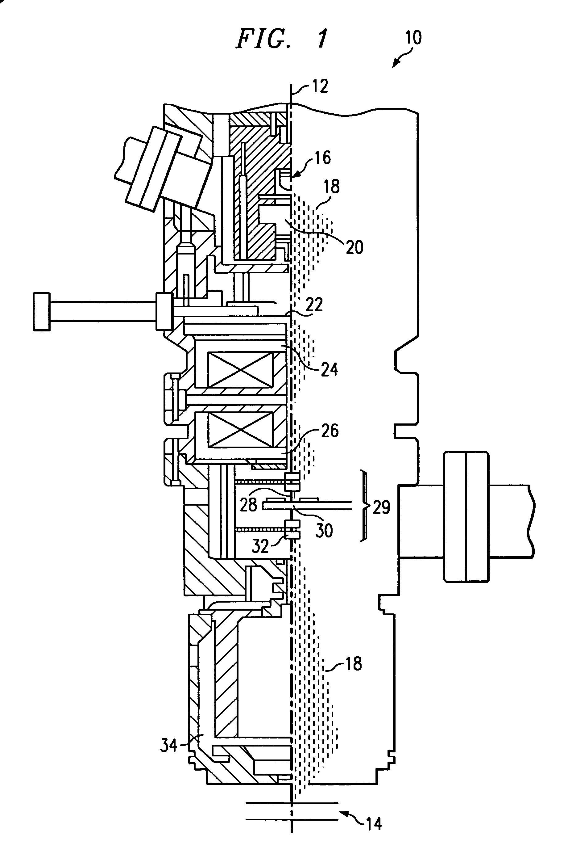
[0031]For general understanding of the invention, it is helpful to see the relationship for the blanker to the other elements of an electron beam lithography column. To that end, FIG. 1 shows a side cut-away schematic view of electron beam lithography system 10 incorporating the teachings of the present invention. Electrons are provided in the column by a cathode which is a thermal field emission electron source 16 much as described in U.S. Pat. No. 3,374,386 entitled FIELD EMISSION CATHODE HAVING TUNGSTEN MILLER INDICES 100 PLAIN COATED WITH ZIRCONIUM, HAFNIUM OR MAGNESIUM ON OXYGEN BINDERS, issued to Charbonnier, et al., in 1968. FIG. 1 shows only half of the column cross-section on the left-hand side of dash line 12. On the right-hand side of dash line 12 appears the electron beam divergence and convergence p...


PUM


Abstract

A method for calibrating the scan amplitude of an electron beam lithography instrument by determining the position of a feature within the scan. The method is effective at the operating frequency of the scan and using a limited bandwidth video signal including the steps of determining the reference feature to be an edge over which the video signal rises abruptly from a background level to a white level. The method turns the beam on only over a short region of the scan and represents the degree of overlap between the beam on portion of the scan and the white part of the feature as the total video signal accumulated in that scan.

Description

RELATED INFORMATION[0001]This application claims priority under 35 U.S.C.§119(e)(1) to provisional application No. 60 / 076,879 filed on Mar. 5, 1998.TECHNICAL FIELD OF THE INVENTION[0002]The present invention relates to electron beam lithography methods and systems and, more particularly, to a method and system for calibrating the scan amplitude of an electron beam lithography instrument.BACKGROUND OF THE INVENTION[0003]The manufacture of electronic integrated circuits relies heavily on the use of image projection techniques to expose resist-coated wafers with light or X-rays. The patterns formed by this exposure determine the various circuit connections and configurations. In any exposure method, accuracy of the projected image is a prime consideration. This accuracy is particularly important in the manufacture of high density random access memories (RAM) in which the yield and ultimately the cost of the components depend heavily on meeting tight exposure placement requirements. Wit...

Claims


Application Information

Patent Timeline
Patent Type & Authority Patents(United States)
IPC IPC(8): G06K9/00H01J37/317
CPCB82Y10/00B82Y40/00H01J37/3174
Inventor PENBERTH, MICHAEL J.PLOWS, GRAHAM S.WOOLFE, ADAM
Owner DUPONT PHOTOMASKS
Why Eureka
Try Eureka