Method for manufacturing low-oxygen copper

a technology of low-oxygen copper and manufacturing method, which is applied in the direction of manufacturing tools, furnace details, furnaces, etc., can solve the problems of low productivity, high construction cost and operating cost, and low efficiency of gas furnaces, so as to achieve the effect of reducing construction cost and operating cost, and reducing production cos

Inactive Publication Date: 2005-09-20
MITSUBISHI MATERIALS CORP
View PDF33 Cites 4 Cited by
  • Summary
  • Abstract
  • Description
  • Claims
  • Application Information

AI Technical Summary

Benefits of technology

[0030]Furthermore, when a dike is provided in the casting trough at which the molten copper passes, the molten copper flows meanderingly in the degassing step, and is stirred by the vigorous flow thereof. That is, the molten copper can be automatically stirred by the flow thereof. As described above, since the molten copper vigorously flows up and down, and right to left, the molten copper passing through the casting trough has good opportunity to be brought into contact with the inert gas, and as a result the efficie

Problems solved by technology

However, there are disadvantages in that the construction cost and the operating cost are high, and productivity is low.
However, when such a gas furnace is used, since combustion is performed in the furnace, i.e., oxidation occurs, the oxidized molten copper must be processed by a reducing treatment.
This is the disadvantage of the gas furnace, which is not observed when a high-frequency furnace is used.
As a result, low-oxygen copper cannot be produced unless oxygen contained in the molten copper is decreased by using a reducing gas and/or an inert gas in a step of transferring the molten copper before the molten copper is fed to a continuous casting machine.
In addition, even when the deoxidizing step described above is performed, holes will be formed in the low-oxygen copper and may result in generating defects such as blisters in some cases.
As a result, the quali

Method used


Image

  • Method for manufacturing low-oxygen copper
  • Method for manufacturing low-oxygen copper
  • Method for manufacturing low-oxygen copper

Examples


first embodiment

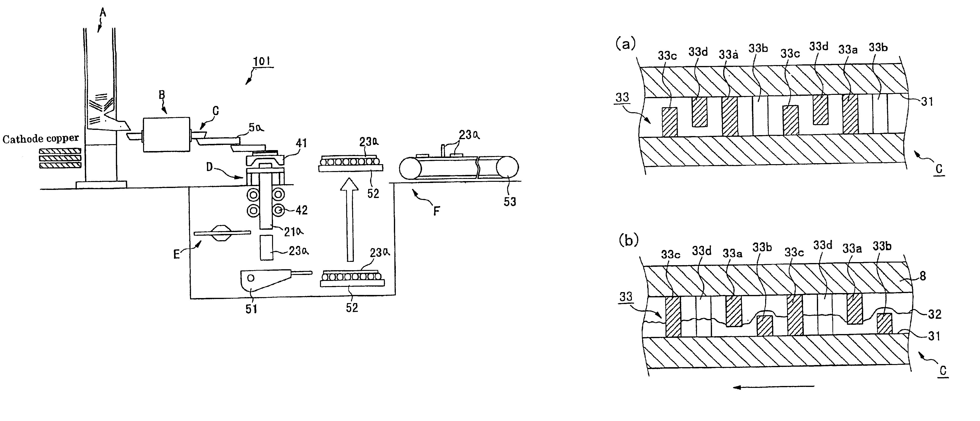
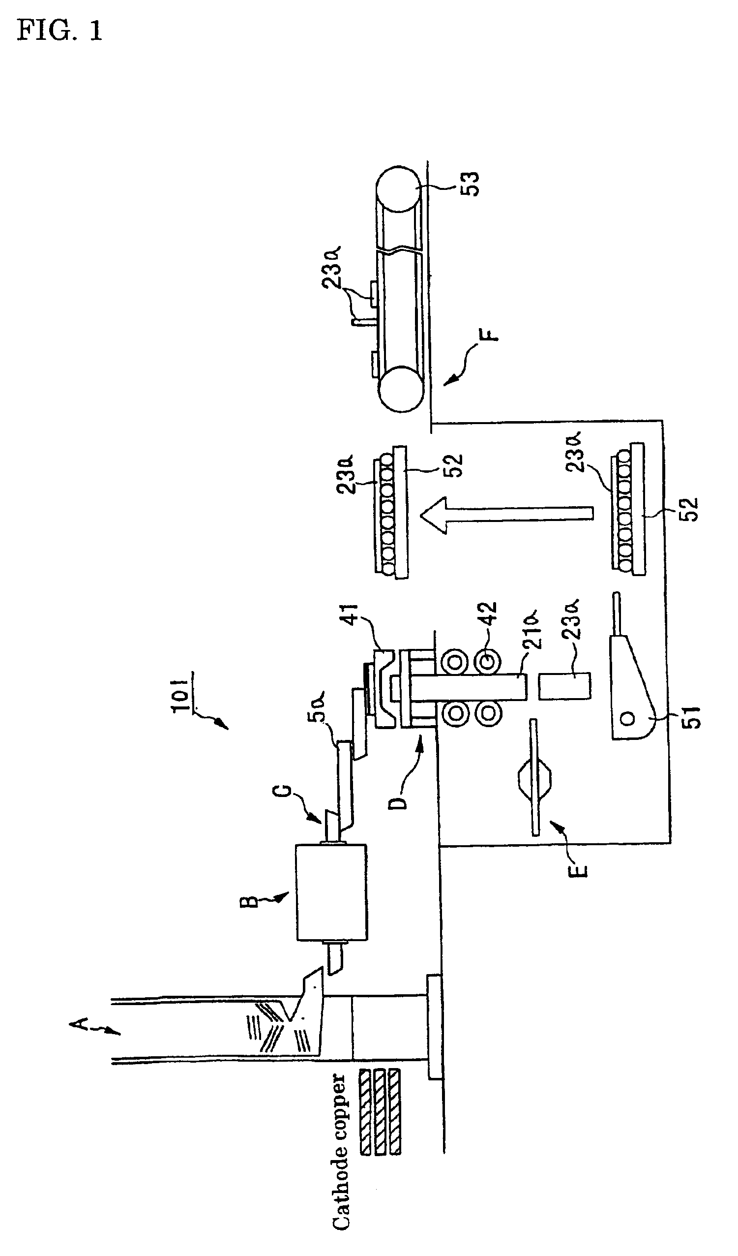
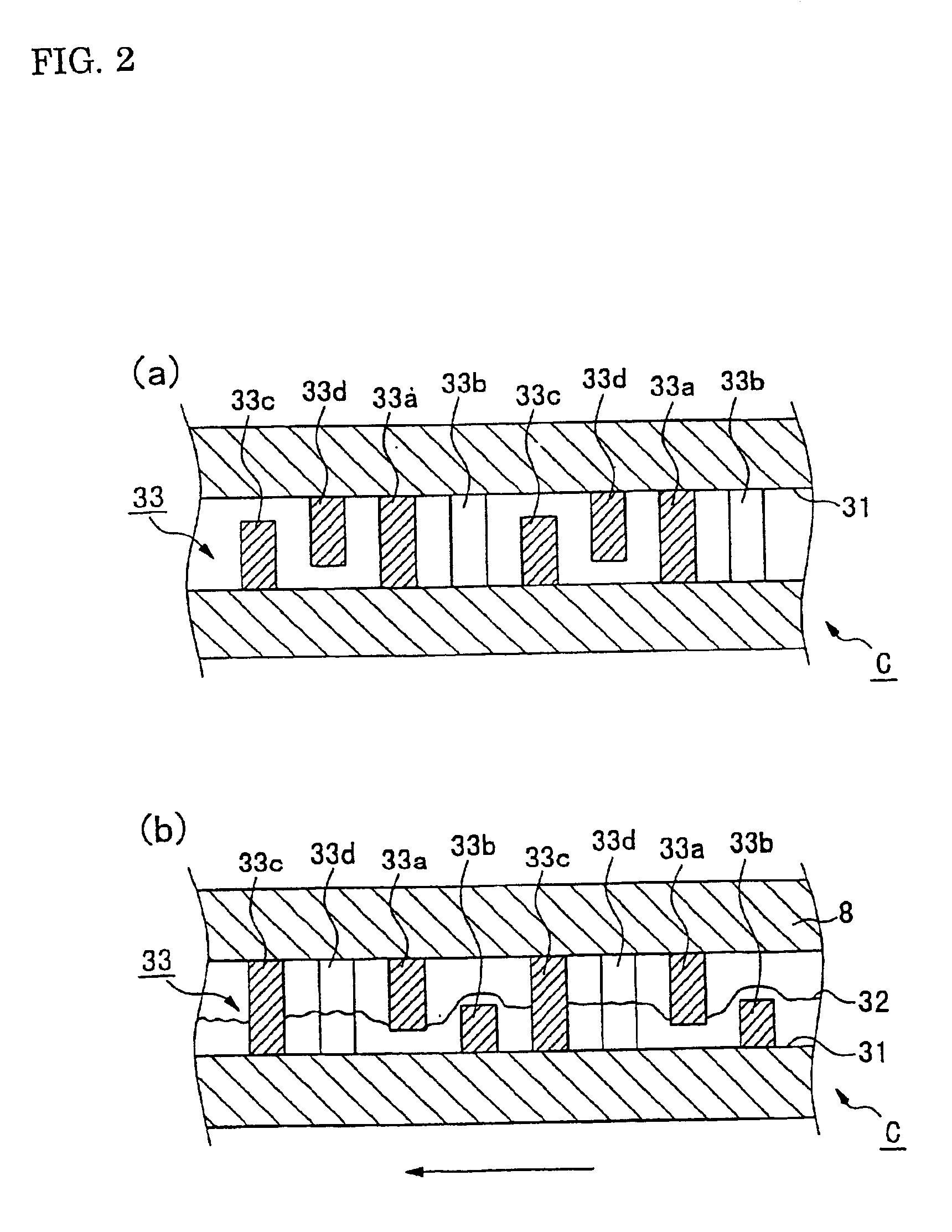
[0042]A first embodiment will first be described with reference to FIGS. 1, 2A, and 2B. This embodiment relates to a method for manufacturing an ingot of low-oxygen copper.

[0043]FIG. 1 is a schematic view showing the structure of an apparatus for manufacturing an ingot of low-oxygen copper, which is used in this embodiment of the present invention, and FIGS. 2A and 2B are enlarged plan and side views, respectively, each showing an important portion in FIG. 1.

[0044]An apparatus for manufacturing an ingot of low-oxygen copper (an apparatus for manufacturing low-oxygen copper) 101 is composed of a melting furnace A, a soaking furnace B, a casting trough C, a continuous casting machine D, a cutter E, and a transfer device F.

[0045]An apparatus for manufacturing an ingot of low-oxygen copper (an apparatus for manufacturing low-oxygen copper) 101 is composed of a melting furnace A, a holding furnace B, a casting trough C, a continuous casting machine D, a cutter E, and a transfer device F....

second embodiment

[0071]Next, a second embodiment will be described with reference to FIGS. 3 and 4. This embodiment relates to a method for manufacturing low-oxygen copper wires.

[0072]FIG. 3 is a schematic view showing the structure of an apparatus for manufacturing low-oxygen copper wires, which is used in this embodiment of the present invention. The apparatus for manufacturing low-oxygen copper wires (an apparatus for manufacturing low-oxygen copper) 102 is primarily composed of a melting furnace A, a holding ace B, a casting trough C2, a belt caster type continuous casting machine G, a rolling machine H, and a coiler I.

[0073]In this embodiment, since the melting furnace and the holding furnace have the structures equivalent to those described in first embodiment, respectively, the same reference levels of the elements in first embodiment designate the same constituent elements in this embodiment, and detailed descriptions thereof will be omitted.

[0074]The casting trough C2 seals the molten liqui...

third embodiment

[0093]Next, a third embodiment will be described with reference to FIGS. 5, and 6A to 6D. This embodiment relates to a method for manufacturing a wire composed of a low-oxygen copper alloy containing silver (Ag).

[0094]The inventors of the present invention discovered through intensive research that by adding a small amount of Ag to molten copper, holes generated in the cast copper alloy containing Ag become finely dispersed micro holes, and that the micro holes thus formed disappear in rolling and do not cause any defects. Accordingly, the generation of holes which is harmful to the wire composed of the low-oxygen copper alloy can be suppressed. In the method for adding Ag, there is still another advantage in that a decrease in the conductivity of wire composed of the low-oxygen copper alloy can also be suppressed.

[0095]FIG. 5 is a schematic view showing the structure of an apparatus for manufacturing the wire composed of the low-oxygen copper alloy which is used in this embodiment ...


PUM


Abstract

A method for manufacturing a low-oxygen copper wire is provided, in which a dehydrogenating treatment can be performed without requiring a long moving distance of molten copper, and the generation of holes in solidification is suppressed, whereby high quality low-oxygen copper wire can be obtained having superior surface quality. The method for continuously manufacturing ingots of low-oxygen copper from molten copper includes a step of performing combustion in a reducing atmosphere in a melting furnace so as to produce molten copper; a step of sealing the molten copper in a non-oxidizing atmosphere in a casting trough; a step of transferring the molten copper to a turn-dish by using the casting trough; a degassing step of passing the molten copper through a degasser provided in the casting trough so as to dehydrogenate the molten copper; a step of continuously feeding the molten copper to a continuous casting machine so as to continuously produce cast copper; and a step of cutting the cast copper into a predetermined length.

Description

CROSS REFERENCE TO RELATED APPLICATIONS[0001]The present application is based on Japanese Application 2000-109827, filed on Apr. 11, 2000, which is hereby incorporated by reference in its entirety.BACKGROUND OF THE INVENTION[0002]1. Field of the Invention[0003]The present invention relates to methods for continuously manufacturing low-oxygen copper, containing a suppressed level of oxygen content, by continuously casting molten copper produced in a melting furnace.[0004]2. Description of the Related Art[0005]Low-oxygen copper (called “oxygen-free copper” in some cases) in which the content of oxygen is controlled to 20 ppm or less, and more preferably, to 1 to 10 ppm, is widely used for producing various shapes, e.g., ingot forms such as billets and cakes, rolled sheets, wires and cut forms. As a method for manufacturing low-oxygen copper, a method is typically used in which molten copper is produced in a high-frequency furnace such as a channel furnace or a coreless furnace, the mo...

Claims


Application Information

Patent Timeline
IPC IPC(8): B22D11/113B22D11/06B22D11/11B22D11/00C22B15/00B22D7/00B22D11/10C22B9/00C22B9/05C22B15/14
CPCB22D11/00B22D11/005B22D11/0602B22D11/11B22D11/113C22B9/05C22B15/006C22B9/006Y10T29/49991Y10S29/005Y10T29/49988Y10T29/49989B22D7/00
Inventor ASAO, HARUHIKOKOSHIBA, YUTAKANOGAMI, KEIJIMASUI, TUTOMUHORI, KAZUMASAWAKIGUCHI, KENJIWADA, MASAHIKOHATTORI, YOSHIAKI
Owner MITSUBISHI MATERIALS CORP
Why Eureka
Try Eureka