
Electromagnetic linear generator and shock absorber

a linear generator and electric technology, applied in mechanical energy handling, transportation and packaging, propulsion systems, etc., can solve the problems of linear generators that do not teach or suggest the use of linear generators as shock absorbers, and the disclosed devices consume rather than generate power, etc., to maximize magnetic flux density, power generation capacity and energy conversion efficiency, and magnetic flux density

Inactive Publication Date: 2005-10-04
TRUSTEES OF TUFTS COLLEGE TUFTS UNIV
View PDF18 Cites 251 Cited by
  • Summary
  • Abstract
  • Description
  • Claims
  • Application Information

AI Technical Summary

Benefits of technology

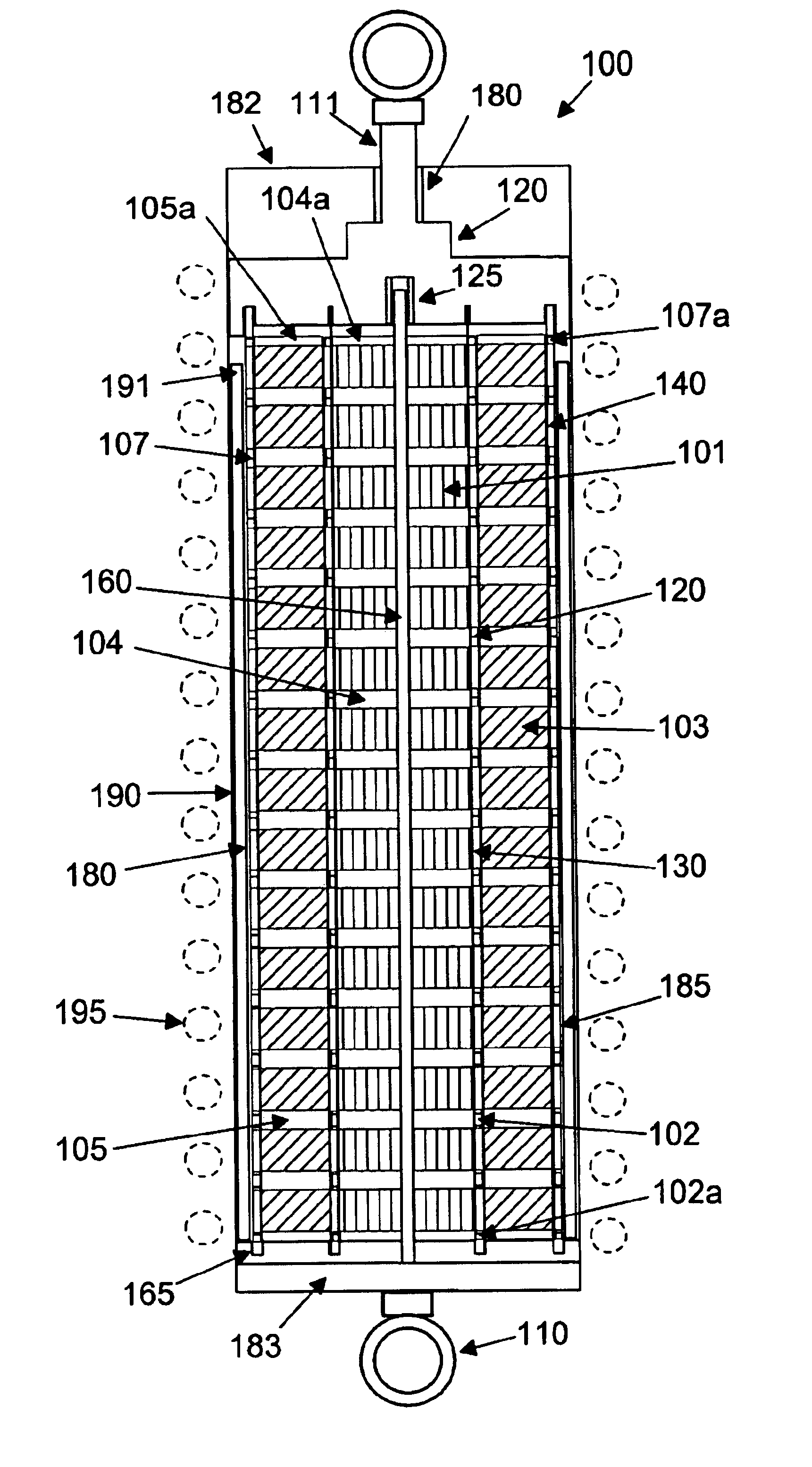
[0027]The linear electromagnetic generator of the present invention uniquely provides for vector superposition of the magnetic field components from a plurality of magnetic fields for maximizing magnetic flux density and electrical power generation from relative motion of a an assembly of coil winding arrays and magnet arrays. The magnetic flux density, power generation capacity and energy conversion efficiency achieved with the innovative design of the present device are substantially higher than typically observed with prior art linear generator devices. The device of the present invention is uniquely suitable for applications as either as a linear motion generator, a reciprocating linear motor or a regenerative electromagnetic shock absorber where electromagnetic damping is exploited.
[0028]The generator device of the present invention comprises a unique assembly of magnet arrays, high magnetic permeability spacers and coil winding arrays with an innovative magnet-spacer-coil configuration and geometry which uniquely provides for vector superposition of the magnetic fields from a plurality of adjacent magnets to maximize radial magnetic flux density within coil windings for optimum power generation and energy conversion efficiency. Unlike conventional electromagnetic devices, as either a linear motion generator, a regenerative shock absorber, or a reciprocating linear motor, the device of the present invention provides for substantially more uniform and higher average radial magnetic flux density throughout coil winding volumes which results in a significant increase in electrical power regeneration due to more efficient generation of induced current from coil motion within regions of maximum radial magnetic flux density.

Problems solved by technology

Fuel consumption for transportation accounts for a considerable portion of total U.S. energy consumption.
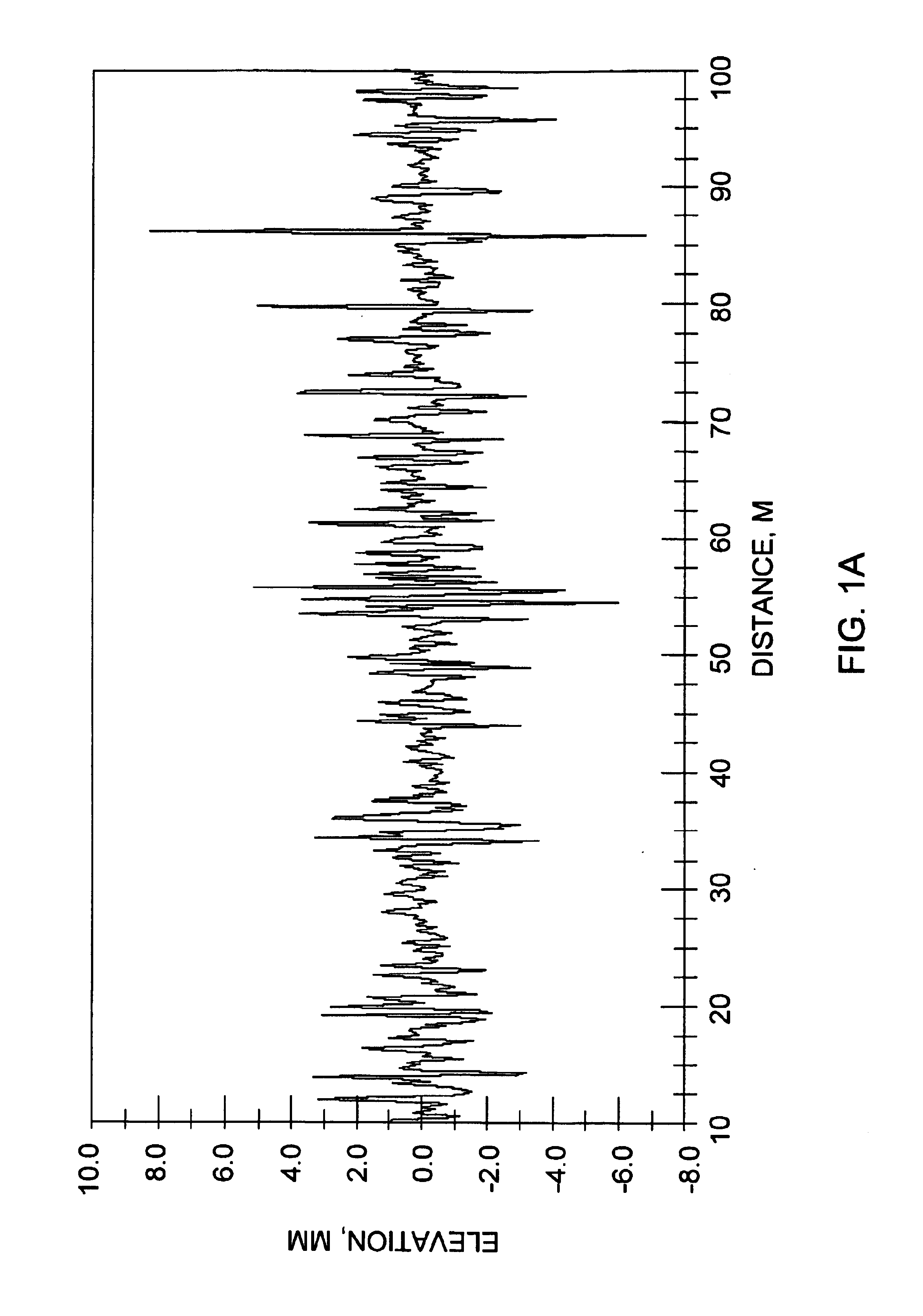
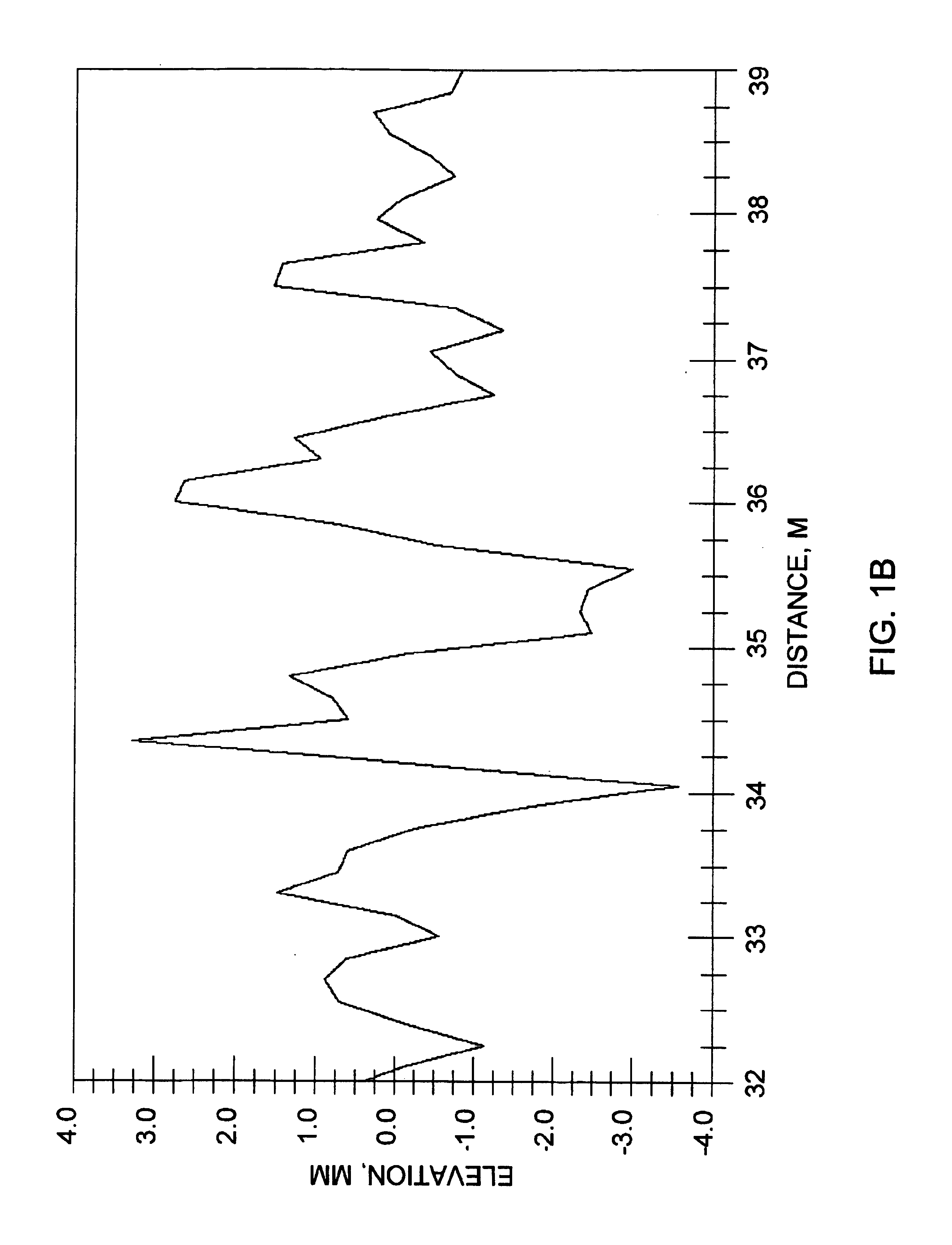
Energy efficiency in both electric and conventional gasoline powered vehicles is generally compromised by road resistance with associated parasitic energy losses caused by mechanical displacements produced by road bumps and road roughness.
The disclosed device dissipates the suspension kinetic energy through a variable load resistance as heat and does not appear to teach or suggest energy recovery and power generation from suspension motion.
The disclosed device consumes rather than generates power.
None of the disclosed devices appear to teach or suggest the use of linear generators as a shock absorber for damping.
One limitation of the disclosed device is that it does not appear to fully utilize the magnetic field and flux created by the magnet array since the generator apparently exploits only single magnetic pole-coil interactions and does not appear to provide for positioning the coil windings in the region of maximum magnetic flux density.
This limitation results in reduced efficiency and power generation capability.
The disclosed device does not appear to fully utilize the magnetic field and flux created by the magnet array since the magnet-coil configuration does not provide for placement of the coil windings in the region of maximum magnetic flux density.
Since Tiemann teaches device enclosures made from ferromagnetic materials to couple to the magnets, the disclosed device will likely produce undesirable eddy currents within the housing enclosure during operation which will significantly dampen motion of the armature, resulting in reduced current output and compromised power generation capacity.
It is anticipated that these limitations will result in a significant reduction in energy conversion efficiency and power generation capability.
One limitation of the disclosed embodiments is that they do not appear to fully utilize the magnetic field and magnetic flux generated from device magnets since the generator designs appear to exploit only single magnetic pole-coil interactions and do not appear to provide for positioning the coil windings in the region of maximum magnetic flux density.
Since the disclosed device apparently relies on natural resonance to drive the device with negligible damping provided, it is unlikely that the disclosed device could function as a shock absorber or provide acceptable power generation capacity and efficiency at the variable bump and displacement frequencies anticipated with vehicles under normal driving conditions on typical road surfaces.
Arsem's device apparently suffers several design limitations which compromise its performance.
In addition, the volume occupied by the iron cores within Arsem's stators substantially reduces both the coil volume and magnetic flux density available to the actual stator coil winding further limiting coil output current and electric power generating capacity.
Since, as shown in FIG. 4 of '027 to Arsem, the predominant portion of the stator coil windings are wrapped around the iron stator cores in a direction perpendicular to the circumferential direction of the induced current flow, most of the coil stator winding volume is wasted since the perpendicularly oriented winding generates essentially no induced circumferential current while substantially increasing coil resistance due to the excessive length of inactive winding, thereby creating undesirable electric power losses due to the substantial joule heating energy losses.
Conventional mechanical devices which attempt to convert suspension displacements from road vibrations and bumps into useful electrical energy suffer from a number of limitations.
Mechanical devices which convert vertical motion into rotary motion for driving conventional generators or alternators typically employ a complex series of rack and pinion gears, levers, clutches, shafts, springs and drive belts which typically have a high weight and space penalty, high mechanical inertia, high displacement response threshold, slow displacement response time, large hysteresis due to requisite mechanical tolerances, and significant energy conversion losses due to heat generated from mechanical friction between components.
Such conventional mechanical motion conversion devices are typically unresponsive to the high frequency, low amplitude bumps and vibrations which are a predominant source of road surface roughness and vertical wheel displacements under typical driving conditions.
Thus, such devices would generally provide relatively low average power generation capability and efficiency under typical urban or highway driving conditions.
The performance of these prior art devices is generally compromised by non-optimized magnet and coil placement and magnetic pole orientations, excessive magnet-coil air gaps, underutilized coil volume, excessive coil resistance, unproductive coil winding orientation, a lack of overlap and combination of magnetic fields from multiple magnets for increased magnetic flux density, reduced magnetic flux density within the coil volume, a lack of accommodation for variable frequency operation to exploit realistic displacement frequencies and amplitudes, inadequate damping and poor matching of device current and voltage output to external electrical power requirements.
Thus, conventional regenerative electromagnetic generator devices do not currently provide for efficient and viable power generation and damping for actual displacements and vibrations encountered under normal driving conditions on typical road surfaces.

Method used


Image

  • Electromagnetic linear generator and shock absorber
  • Electromagnetic linear generator and shock absorber
  • Electromagnetic linear generator and shock absorber

Examples


Embodiment Construction

A. Principle of Operation

1. Electromagnetic Power Generation

[0062]The power generating performance of a linear electromagnetic generator or regenerative electromagnetic shock absorber of the present invention is based upon the well known electromagnetic principle that an electric charge q moving through a magnetic field {overscore (B)} experiences a Lorentz force {overscore (F)}L equal to the product of the cross product of the velocity vector {overscore (V)} and magnetic field {overscore (B)} and electric charge q

{overscore (F)}L=q·({overscore (V)}×{overscore (B)})

and a corresponding Lorentz electric field EL equal to the product of the cross product of the velocity vector {overscore (V)} and magnetic field {overscore (B)}

ĒL={overscore (V)}×{overscore (B)}

where {overscore (V)} is the velocity vector of the charge, {overscore (B)} is the magnetic field of a magnet and q is the charge in coulombs. This principle also applies to a coil of wire moving in a radial magnetic field.

[0063]C...


PUM


Abstract

An electromagnetic linear generator and regenerative electromagnetic shock absorber is disclosed which converts variable frequency, repetitive intermittent linear displacement motion to useful electrical power. The innovative device provides for superposition of radial components of the magnetic flux density from a plurality of adjacent magnets to produce a maximum average radial magnetic flux density within a coil winding array. Due to the vector superposition of the magnetic fields and magnetic flux from a plurality of magnets, a nearly four-fold increase in magnetic flux density is achieved over conventional electromagnetic generator designs with a potential sixteen-fold increase in power generating capacity. As a regenerative shock absorber, the disclosed device is capable of converting parasitic displacement motion and vibrations encountered under normal urban driving conditions to a useful electrical energy for powering vehicles and accessories or charging batteries in electric and fossil fuel powered vehicles. The disclosed device is capable of high power generation capacity and energy conversion efficiency with minimal weight penalty for improved fuel efficiency.

Description

FIELD OF THE INVENTION[0001]This invention relates generally to linear motion energy recovery and energy conversion generators. More particularly, this invention relates to efficient, variable frequency, electromagnetic generators for converting parasitic intermittent linear motion and vibration into useful electrical energy. Most particularly, this invention relates to regenerative electromagnetic shock absorbers which both dampen displacement motion and vibrations and convert these into useful electrical energy.BACKGROUND OF THE INVENTION[0002]Fuel consumption for transportation accounts for a considerable portion of total U.S. energy consumption. The efficiency of conventional gasoline powered vehicles has been estimated at less than ten percent based on energy delivered to the drive train wheels [see Efficient Use of Energy, K. W. Ford, et al. (eds.), American Institute of Physics (New York 1975), p 99-121, which is incorporated herein by reference]. Vehicle efficiency is furthe...

Claims


Application Information

Patent Timeline
Patent Type & Authority Patents(United States)
IPC IPC(8): B60G17/015F16F15/03H02K35/00H02K35/04
CPCB60G17/0157F16F15/03H02K35/04B60G2202/42B60G2300/60B60G2600/26
Inventor GOLDNER, RONALD B.ZERIGIAN, PETER
Owner TRUSTEES OF TUFTS COLLEGE TUFTS UNIV
Learn More