Ultra low power plasma reactor system for automotive NOx emission control

a plasma reactor and low-power technology, applied in the direction of machines/engines, mechanical equipment, separation processes, etc., can solve the problems of prohibitively large power requirements for plasma reactors, increase in input energy above a certain value, and hardly improve the overall performance of plasma processes, etc., to promote axial mixing of ionized reaction intermediates, the effect of reducing the energy consumption in relation to the production of aldehydes

Inactive Publication Date: 2005-11-01
GM GLOBAL TECH OPERATIONS LLC
View PDF11 Cites 24 Cited by
  • Summary
  • Abstract
  • Description
  • Claims
  • Application Information

AI Technical Summary

Benefits of technology

[0014]In operation, the inner electrode is connected to a source of varying high voltage and the outer electrode to ground, thereby providing successive active regions and passive regions axially along the hyper-plasma reactor. The incoming air mixed with hydrocarbons goes through plasma reactions at each active region, followed by a chemical reaction relaxation in the following passive region. In this regard, because each active region is axially compact, an intense generation of energetic electrons occurs thereat; because each passive region is axially extended, sufficient time is provided for the resulting oxidation processes before the next active region is encountered. Accordingly, the energy consumption in relation to the production of aldehydes is extremely favorable.
[0015]This favorable result can be explained as follows. Since the ion and radical velocity depends on the strength of the electric field, these velocities in the radial direction (transverse to the axial direction) are faster in the active regions than in the passive regions. This velocity gradient in the radial direction, with the help of the spatially alternating electric field, promotes axial mixing of ionized reaction intermediates, resulting in an enhanced reactivity with the hydrocarbons. This mixing, in turn, means

Problems solved by technology

However, when the rate limiting step is other than the electron supply, an increase in input energy above a certain value through the continuous electrodes will hardly improve the overall performa

Method used


Image

  • Ultra low power plasma reactor system for automotive NOx emission control
  • Ultra low power plasma reactor system for automotive NOx emission control
  • Ultra low power plasma reactor system for automotive NOx emission control

Examples


Embodiment Construction

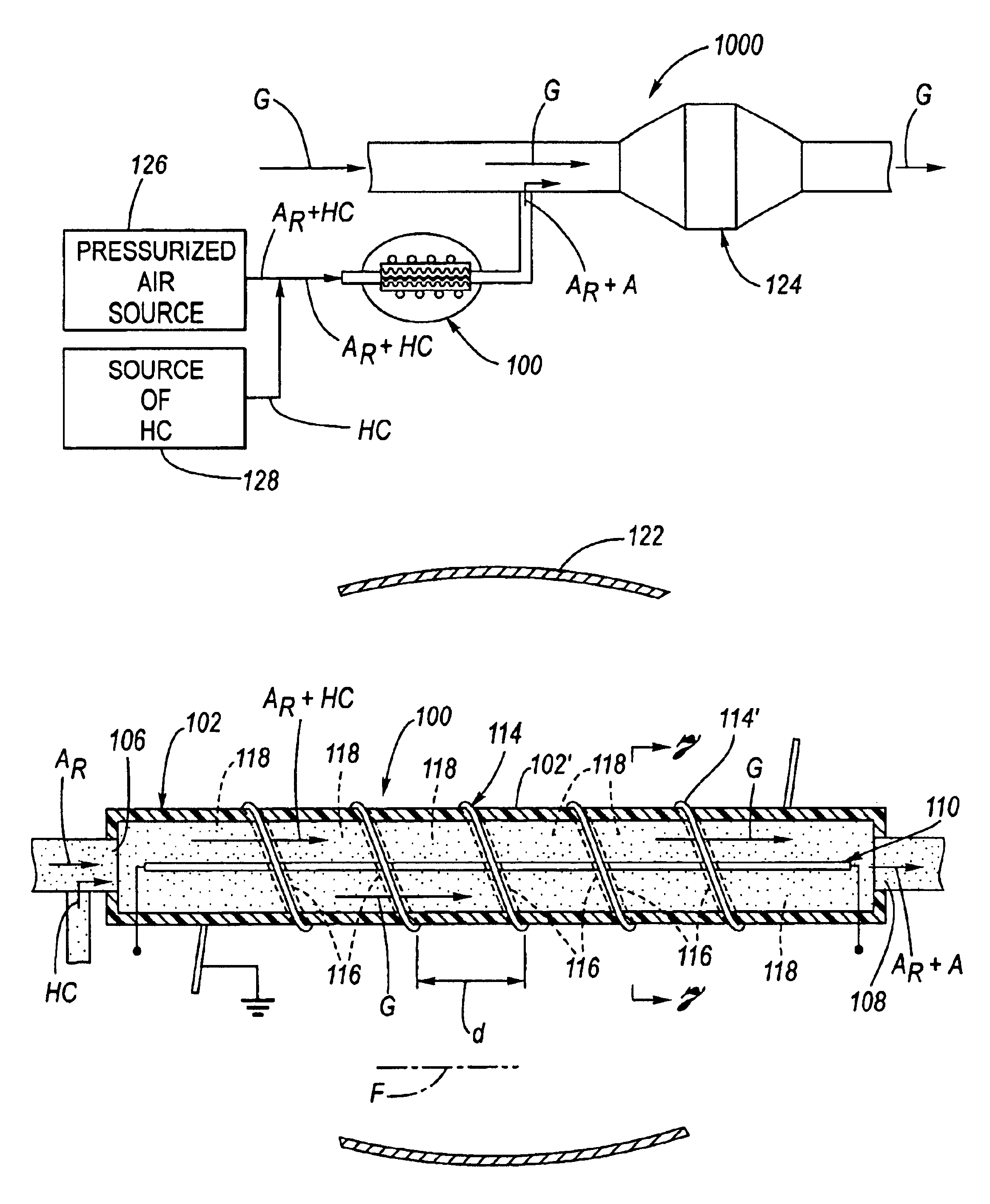
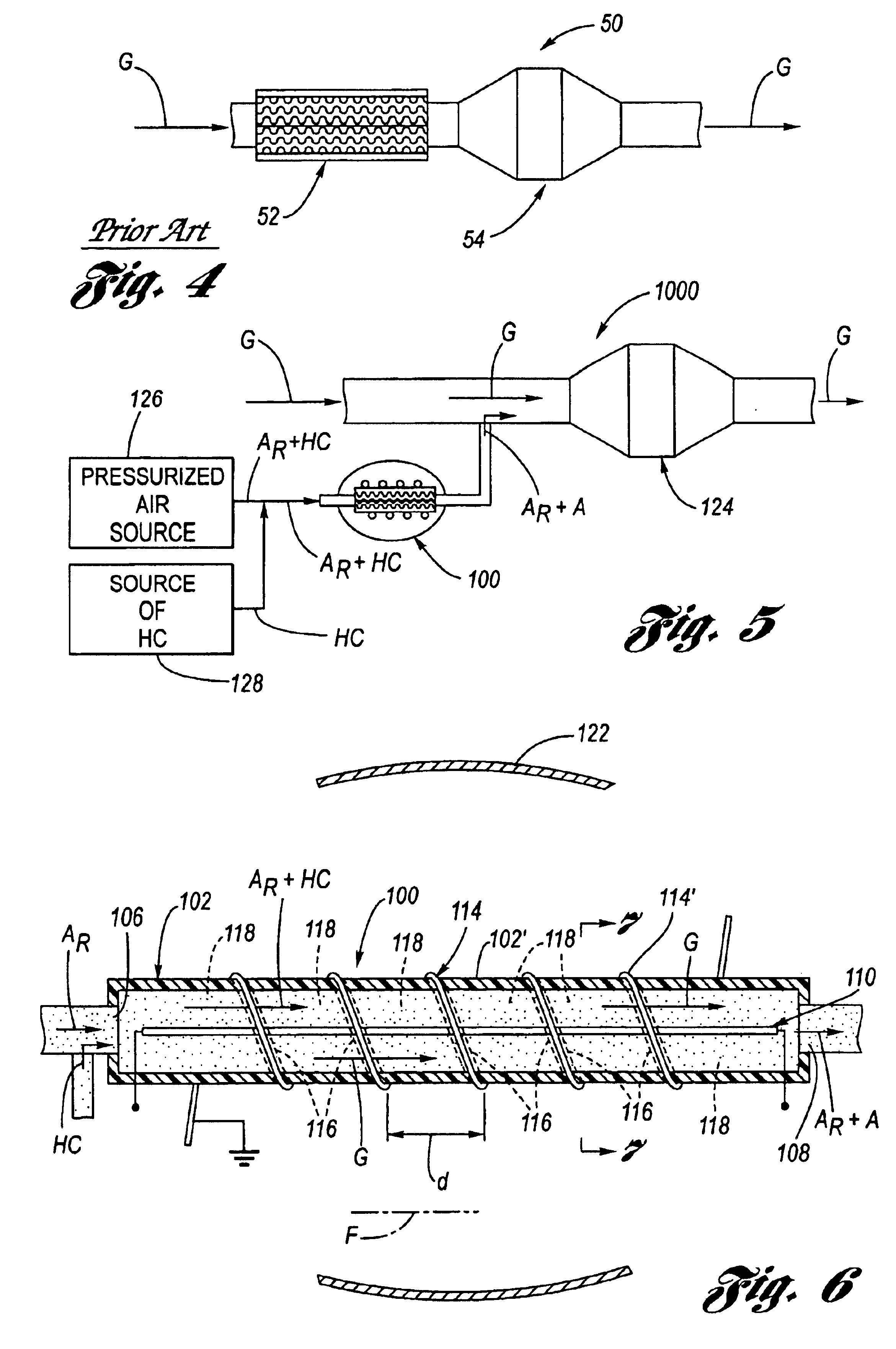
[0027]Referring now to the Drawing, FIGS. 5 through 16 depict various aspects of an example of an automotive exhaust gas hyper-plasma reactor and catalytic converter system 1000 according to the present invention, wherein a hyper-plasma reactor 100 thereof features serially alternating regions of active and passive electric field along its axial length, and wherein the hyper-plasma reactor is located in a sidestream relationship with respect to the main exhaust stream, as shown at FIG. 5.

[0028]As depicted at FIGS. 6 through 9, the hyper-plasma reactor 100 according to the present invention has an elongated cylindrical configuration defined by a plasma reactor wall 102 composed of an insular dielectric material 102′ which serves as a dielectric barrier and defines a reactor space thereinside. The composition of the plasma reactor wall 102 may be any suitable dielectric material, as for example quartz, glass, alumina, etc. By way merely of exemplification and not limitation, the diele...


PUM

PropertyMeasurementUnit
Fractionaaaaaaaaaa
Fractionaaaaaaaaaa
Volumeaaaaaaaaaa

Abstract

A sidestream located hyper-plasma reactor having an axially discrete pattern of alternating regions of active and passive electric field along the axial direction. The hyper-plasma reactor has great efficacy in terms of ultra low power consumption and copious production of NOx converting aldehydes in the absence of NO by applying plasma power only to an air and hydrocarbon mix sidestream gas flow. Only a small fraction (1% to 2%) of plasma power is required as compared to that for a conventional plasma reactor to treat the full exhaust gas stream. The hyper-plasma reactor produces ozone which reacts subsequently with hydrocarbons to produce aldehydes (“ozonolysis”). The sidestream location of the hyper-plasma reactor allows for the full exhaust stream to bypass it, without significantly affecting the overall NOx conversion performance in the catalytic converter.

Description

TECHNICAL FIELD[0001]The present invention relates to plasma reactors and catalytic converters used to reduce NOx of internal combustion engine exhaust, and more particularly to a plasma reactor and catalytic converter based NOx reduction system featuring a hyper-plasma reactor operating at an ultra low power placed in a side-stream location in relation to the main exhaust stream for producing copious amounts of NOx reducing aldehydes upstream of the catalytic converter.BACKGROUND OF THE INVENTION[0002]The removal of nitrogen oxides (NOx) from internal combustion exhaust is an increasing concern, especially for lean-burn engines such as direct injection gasoline engines and Diesel engines. One method for post combustion NOx removal is the subjection of the exhaust gases to a non-thermal plasma process. In this regard, the exhaust gas is passed through a plasma processing device whereat a high voltage electric field imparts formation of a plasma. The plasma has a large number of ener...

Claims


Application Information

Patent Timeline
IPC IPC(8): F01N3/20
CPCB01D53/323F01N3/0892F01N3/2066B01D2251/104B01D2257/404B01D2258/012B01D2259/818F01N2240/28F01N2610/03F01N2610/08Y02T10/24Y02T10/12
Inventor CHO, BYONG KWONSCHMIEG, STEVEN JEFFREYOH, SE HYUCK
Owner GM GLOBAL TECH OPERATIONS LLC
Why Eureka
Try Eureka