Liquid ink and recording apparatus

a liquid ink and recording device technology, applied in the direction of instruments, optical elements, inks, etc., can solve the problems of difficult to solve the contamination problem of the surrounding atmosphere, the printing surface of the printing paper sheet, etc., and seriously affect the quality of the printed image, etc., to achieve high-quality printing

Inactive Publication Date: 2005-11-01
TOSHIBA TEC KK
View PDF18 Cites 54 Cited by
  • Summary
  • Abstract
  • Description
  • Claims
  • Application Information

AI Technical Summary

Benefits of technology

[0016]An object of the present invention is to provide a liquid ink which does not necessitate the use of an organic solvent and which does not necessitate a bulky light exposure system for obtaining a high quality print.

Problems solved by technology

In this technique, however, an organic solvent is evaporated in an amount that cannot be neglected in the case of printing images on a reasonably large amount of paper sheets.
As a result, the surrounding atmosphere is contaminated with the evaporated organic solvent, which makes it necessary to arrange an exhaust facility or a solvent recovery mechanism.
Therefore, in the technique described above, it is necessary for the solvent concentration in the ink to be set at a sufficiently high level, with the result that it is essentially difficult for this technique to solve the contamination problem of the surrounding atmosphere caused by from the evaporated organic solvent.
It should also be noted that, in the case of using a solvent system ink, the printing surface of the printing paper sheet, etc., seriously effects the quality of the printed images.
For example, the printing surface having a permeability tends to cause the printed images to be blurred, and it is difficult to fix the printed images to the printing surface that is not permeable.
Further, a reasonably long time is required for the ink layer formed on the printing surface to be dried.
Therefore, in the case of forming a thick image on a large printing surface, the image tends to be collapsed because of the fluidity of the ink.
In addition, in the technique using a solvent described above, the printing surface tends to be deteriorated by the drying of the ink layer.
It follows that it is not necessarily easy to obtain a high quality print by this technique.
However, the ink used in this technique contains a large amount of cancer-causing components such as a radical generating agent.
In addition, the volatile acrylic acid derivative used as a radical polymerizable monomer is highly irritating to the skin and is highly odorous.
In addition, the pigment contained in the ink absorbs the light irradiating the ink layer, with the result that the dose of the light tends to be rendered insufficient in the deep portion of the ink layer.
Under the circumstances, the conventional radical polymerizable ink is low in its sensitivity to light and, thus, a very large light exposure system is required for obtaining a high quality print by this technique.
However, the conventional photosensitive ink of this type contains a solvent, which gives rise to the problem in terms of the release of the solvent into the environment.
In addition, the ink tends to be easily cured spontaneously and change to be insoluble, giving rise to an additional problem that tends to plug ink-jet nozzle.
It follows that a serious problem remains unsolved in terms of the release of the photosensitive composition into the environment.
The ink for ink jet also contains as an indispensable component a specified vinyl ether compound having a very high volatility, giving rise to a problem similar to that described above.
Also, the ordinary vinyl ether compound, when used in combination with a pigment, gives rise to a problem that the compound is poor in polymerizability.
Also, it is difficult to uniformly disperse the pigment in the ink.
Therefore, in this technique, there are the large problems in dispersing and in stabilizing pigments.
Therefore, it is necessary to use a special high-cost micro capsule type pigment, or in usual case, coloring component is limited to a dye which tends to be de-colored with time.
It follows that the ink jet recording apparatus referred to above is not adapted essentially for the printing of a color image.
What should also be noted is that, particularly in the case where the printing surface is formed of an absorbent medium, a serious problem is generated that the conventional acrylic photo-curable ink jet ink is unlikely to be set inside the absorbing paper sheet.
Incidentally, the conventional cationic photo-curable ink jet ink gives rise to the problem that the viscosity of the ink is vigorously changed spontaneously.
The problem is derived from the situation that, if an acid is once generated in the ink by the deterioration of the ink with time, the ink is unlikely to be deactivated so as to bring about much dark reactions in the ink.
The problem is very serious because, if the viscosity is changed in the ink jet ink, a fatal situation such as a disturbance in the flying shape of the ink, a poor printing reproducibility and, in the worst case, a poor spurting of the ink and the ink plugging in nozzle tends to take place.

Method used


Image

  • Liquid ink and recording apparatus
  • Liquid ink and recording apparatus
  • Liquid ink and recording apparatus

Examples


example i

Example I-1

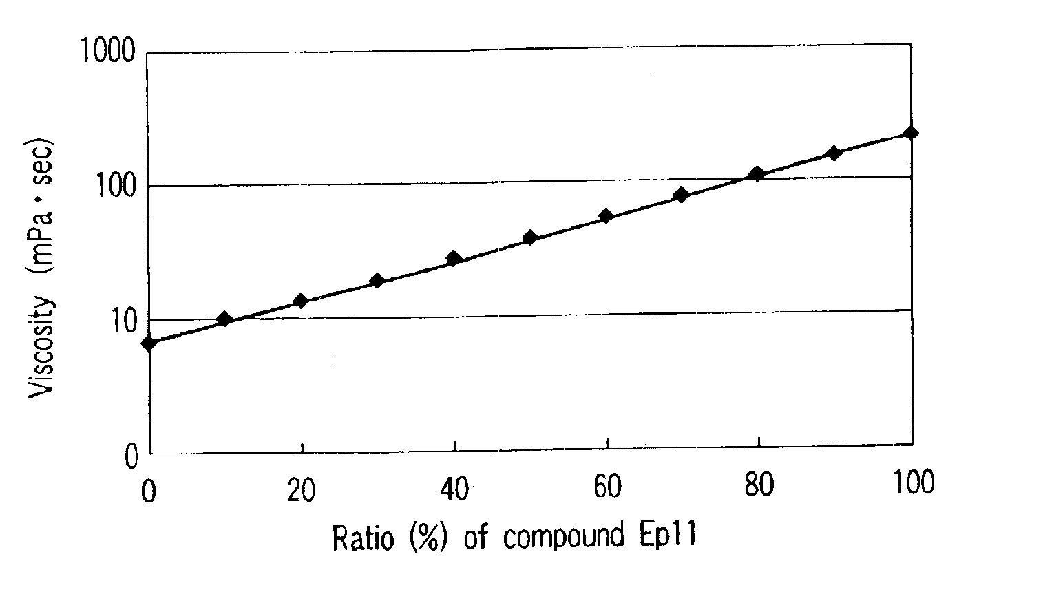
[0238]Compositions a1 to j1 were prepared by mixing acid polymerizable compounds (and resins) Ep1 to Ep16 given below, i.e., compounds polymerizable in the presence of an acid, in the mixing ratio given in Table 1:

Each of 1, m and n in the general formulas given above denotes an integer falling within a range of between 1 and 20.

[0239]

TABLE 1EpoxycompositionEpoxy compounds (% by weight)a1Ep3(100)b1Ep3(87.5)Ep11(12.5)c1Ep3(80)Ep11(10)Ep16(10)d1Ep2(70)Ep10(20)Ep12(10)e1Ep1(80)Ep9(10)Ep16(10)f1Ep7(50)Ep3(30)Ep10(10)Ep16(10)g1Ep3(40)Ep8(30)Ep13(10)Ep14(10)h1Ep3(40)Ep4(40)Ep11(12.5)Ep15(7.5)i1Ep6(50)Ep3(30)Ep11(10)Ep16(10)j1Ep5(30)Ep3(40)Ep12(20)Ep15(10)

[0240]A pigment and a photo acid generating agent were added to each of the compositions a1 to j1 by the prescriptions shown in Table. 2 below, and a dispersion treatment was applied for 24 hours by using a paint shaker. The mixture after the dispersion treatment was filtered by using a PTFE filter of 5 μm so as to obtain liqu...

example i-2

[0269]In the first step, compositions aa to ap were prepared by mixing acid polymerizable compounds (and resins) Ep21 to Ep38 given below in the mixing ratios shown in Table 4:

[0270]

Table 4Ep21Ep22Ep23Ep24Ep25Ep26Ep27Ep28Ep29Ep30Ep31Ep32Ep33Ep34Ep35Ep36Ep37Ep38CompositionsCompounds (% by weight)Liquid inksaaEp21 (87.5)Ep11 (12.5)(41)abEp22 (87.5)Ep11 (12.5)(42)acEp3 (50)Ep23 (50)(43)adEp3 (50)Ep24 (50)(44)aeEp3 (90)Ep27 (10)(45)afEp3 (50)Ep26 (50)(46)agEp3 (40)Ep25 (30)Ep28 (30)(47)ahEp3 (35)Ep28 (35)Ep29 (30)(48)aiEp3 (40)Ep30 (40)Ep29 (20)(49)ajEp3 (40)Ep28 (60)(50)akEp3 (40)Ep31 (40)Ep32 (30)(51)alEp3 (40)Ep33 (40)Ep34 (30)(52)amEp3 (40)Ep32 (40)Ep37 (30)(53)anEp3 (40)Ep26 (40)Ep36 (30)(54)aoEp3 (40)Ep32 (40)Ep35 (30)(55)apEp3 (40)Ep37 (30)Ep38 (30)(56)

[0271]Added to each of the compositions aa to ap were 5% by weight of carbon black used as a pigment and 8% by weight of UVACURE 1591 used as a photo acid generating agent, and each of the resultant mixtures was subjected to a disp...

example i-3

[0285]Kneaded was a mixture comprising a Co-γ-Fe2O3 powder pulverized to have a particle diameter of 500 nm, an acrylic dispersion used as a dispersant, an amphoteric resin used as an electrostatic processing agent, and traces of a metal soap, followed by dispersing the kneaded mass in the epoxy compound (Ep2) by using a paint shaker such that kneaded mass was contained in an amount of 5% by weight relative to the epoxy compound (Ep2). Further, PAG5 used as a photo acid generating agent was added in an amount of 8% by weight based on the epoxy compound, and the resultant mixture was filtered by using a PTFE filter of 5 μm so as to obtain a functional ink composition 1.

[0286]The functional ink composition thus obtained was spurted onto an absorbing medium, followed by exposing the absorbing medium to light at an exposing rate of 500 mJ / cm2 and subsequently heating the absorbing medium at 100° C. for 3 minutes. As a result, a magnetic pattern was formed on the medium. The magnetic pat...


PUM

PropertyMeasurementUnit
boiling pointaaaaaaaaaa
viscosityaaaaaaaaaa
intrinsic viscosity ηtaaaaaaaaaa

Abstract

There is disclosed a liquid ink including a photo acid generating agent that generates an acid upon irradiation with light, a coloring component, and at least one kind of a solvent that is polymerized in the presence of an acid. It is preferable that the amount of the photo acid generating agent contained in the liquid ink falls within a range of between 1 part by weight and 10 parts by weight relative to 100 parts by weight of the solvent, the coloring component consists of a pigment, and the solvent contains at least 50 parts by weight of an acid polymerizable compound, the acid polymerizing compound polymerizing in the presence of the acid, having an alicyclic skeleton and / or an aliphatic skeleton having a viscosity of 50 mPa·s or less and a boiling point of 150° C. or more under room temperature and atmospheric pressure.

Description

CROSS-REFERENCE TO RELATED APPLICATIONS[0001]This application is based upon and claims the benefit of priority from the prior Japanese Patent Application No. 2002-122864, filed Apr. 24, 2002; and No. 2003-004862, filed Jan. 10, 2003, the entire contents of both of which are incorporated herein by reference.BACKGROUND OF THE INVENTION[0002]1. Field of the Invention[0003]The present invention relates to a liquid ink and an ink jet recording apparatus.[0004]2. Description of the Related Art[0005]A printing machine utilizing a printing plate has been used for the manufacture of a print requiring a reasonably large number of prints such as a local advertisement, materials for distribution within an enterprise, or a large poster. In recent years, an on-demand printing machine, which is capable of dealing with diversified needs and compressing the stock, has come to be used in place of such a conventional printing machine. An electrophotographic printing machine using a toner or a liquid t...

Claims


Application Information

Patent Timeline
Patent Type & Authority Patents(United States)
IPC IPC(8): B41J11/00B41J2/005C08G65/00C08G65/14C08G65/18C09D11/00B41J2/01B41M5/00C09D11/322C09D11/324C09D11/328C09D11/36C09D11/38
CPCB41J2/0057B41J11/002C08G65/14C08G65/18C09D11/101C09D11/30C09D11/322C09D11/38B41M7/0081B41J11/00214B41J11/00216
Inventor USHIROGOUCHI, TORUTANUMA, CHIAKIOHTSU, KAZUHIKOAKIYAMA, RYOZOHIROKI, MASASHIENDO, YOSHITO
Owner TOSHIBA TEC KK
Why Eureka
Try Eureka