Waveform independent high frequency power system

a power system and waveform technology, applied in the direction of electric variable regulation, process and machine control, instruments, etc., can solve the problems of low operating voltage of microprocessors, serious electrical consequences, and abrupt change of current drawn by the processor, and achieve the effect of low inductance connections

Inactive Publication Date: 2005-11-01
INTEGRATED DEVICE TECH INC
View PDF70 Cites 21 Cited by
  • Summary
  • Abstract
  • Description
  • Claims
  • Application Information

AI Technical Summary

Benefits of technology

[0029]It is an object of the present invention, therefore, to provide a means for storing energy with lower inductance connections than could be achieved with the prior art. It is a further object of the present invention to provide a source of energy at low voltage and high current which does not need to be placed in very close proximity to the electronic load. Similarly, it is yet an another object of the invention to provide a source of low voltage which can sustain the voltage across the powered load even in the presence of high rates of change of current draw
[0030]It is also an object of the present invention, to provide a means of converting utility power to high frequency alternating power for efficient distribution at higher efficiency than can be achieved using existing techniques. It is also an object to provide a means of converting high frequency ac power to the low dc voltages and high de currents required by current and future electronics at higher efficiency than can be achieved using current techniques. It is another object of the present invention to maintain that efficiency over a wide range of load conditions.

Problems solved by technology

As the chip designers push to higher and higher speeds, problems arise which relate to thermal issues.
So there is a tendency to lower the operating voltage of microprocessors.
This can produce an abrupt change in the current drawn by the processor, which has serious electrical consequences.
The energy stored in the system is supplied by the source of electrical current, and for a given power source there is a limit to the rate at which energy can be supplied, which means that the stored energy must be built up over time.
Thus the presence of an energy storage mechanism naturally slows down a circuit, as the energy must be produced and metered into the magnetic field at some rate before the current can build up.
While it might be suggested that capacitors might be used to supply energy during the delay interval required for the current in the conductors to rise, the intrinsic inductance of the connections to the capacitors currently severely limits this approach.
This requirement will become increasingly severe as the voltages drop still further and the currents increase, because the former reduces the allowable transient size and the latter increases the potential rate of change of current.
Both factors reduce the permissible inductance of the connection.
This can force the designer to use smaller capacitors which have low inductance connections, and because the smaller capacitors store less energy, this drives the power system to higher frequencies, which adds costs and lowers efficiency.
While it is possible to create a low voltage regulated dc power source using simple transformers, rectifiers, and linear regulators, such units would be heavy, bulky and inefficient.
In these applications it is desirable to reduce weight and size, and this approach is unsuitable for this reason alone.
In addition, the inefficiency of linear regulators is also unacceptable.
Efficiency is defined as the ratio of output power to input power, and a low efficiency implies that heat is being developed in the unit which must be transferred to the environment to keep the unit cool.
The resulting overall system is complex and not very efficient, in spite of the use of switchmode technology.
Substantial additional losses may be sustained in the low voltage conversion process.
Other voltage regulation modules will have losses almost as great, resulting in losses for the entire system which may be one-third of the power used.
Some particularly inefficient approaches may demonstrate efficiencies as low as 50%, requiring that the input power circuits utilize twice the power required by the actual final circuitry, and requiring that twice the heat be dissipated in the electronics (which must be removed by a fan) as is theoretically required by the actual operating circuitry.
This system evolved over the years and is not optimum for many current uses, but persists because of inertia of the industry and because of the perceived benefit of maintaining industry standards on voltages and currents as generated by the central power unit.
An analysis of current trends in the microprocessor industry clearly indicates that the current system will not be adequate for the future.
A further problem in the prior art is the use of square wave electronic conversion techniques.
These edges produce high frequency power components which can be conducted or radiated to adjacent circuitry, interfering with their proper operation.
These high frequency power components may also be conducted or radiated to other electronic equipment such as radio or television receivers, also interfering with their proper operation.
The presence of such components requires careful design of the packaging of the power system to shield other circuitry from the high frequency power components, and the installation of expensive and complex filters to prevent conduction of these components out of the power supply package on its input and output leads.

Method used


Image

  • Waveform independent high frequency power system
  • Waveform independent high frequency power system
  • Waveform independent high frequency power system

Examples


examples

[0184]Choosing all the circuit parametric values can be a lengthy task. The following example is a general-purpose rectifier which maybe optimized for powering a microprocessor operating at 1.8 volts and requiring 20 amperes. Using the circuit of FIG. 3-3 the following parametric values may be appropriate:

[0185]

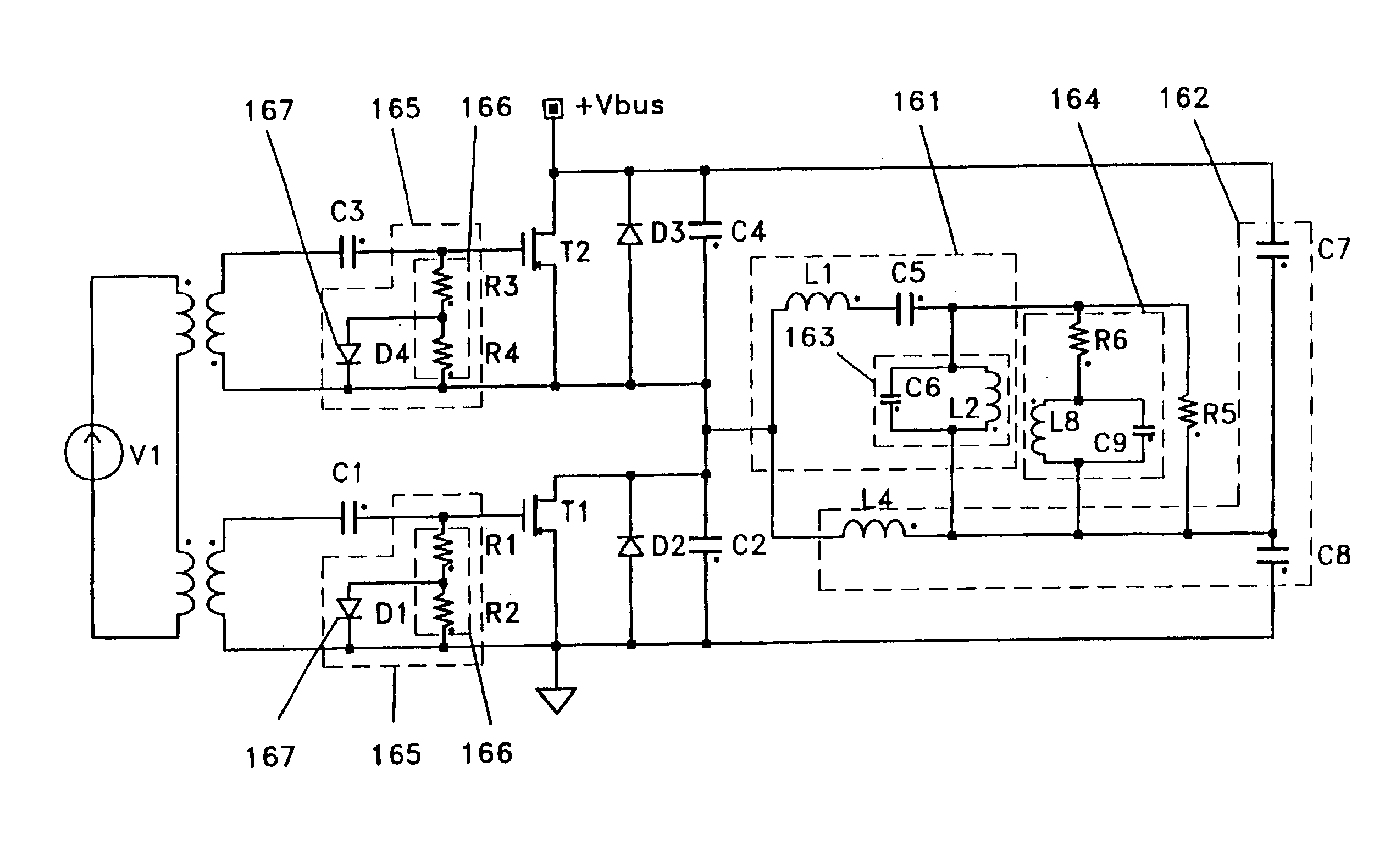
Frequency3.3MHzTurns ratio5:1Input voltage30VACLT30nHCT10nFCin2nFL1 & L2100nHCo500μFSR1 & SR23ea. FDS6880Conduction angle266degreesDelay angle24degrees

[0186]FIG. 3-5 shows one embodiment of a SR gate drive; it consists of summation of sinusoidal signal derived from the AC input plus a control signal. Also, the signal derived from the AC input can have an optimal delay for high efficiency. This circuit can produce a clean ac voltage by taking advantage of the gate transformer leakage inductance and the gate capacitance to filter harmonics from the ac input. This circuit can also show the creation of delay using R1,2, the combination of C1,2 (which includes the adjunct gate to ...


PUM


Abstract

Method and apparatus are disclosed for providing a constant voltage, high frequency sinusoidal output across a varying load, using either a single or multiple switch topology operating at constant frequency while maintaining high efficiency over the entire load range. This embodiment is especially suited to applications which require the sinusoidal voltage be held very close to a desired value in the presence of rapid changes in the conductance of the load, even in the sub-microsecond time domain as is common in computer applications and the like and in powering electronics equipment, especially a distributed system and especially a system wherein low voltage at high current is required. Embodiments and sub elements provide energy storage for low voltage, high current electronic loads, an ability to supply current with rapid time variation, connection of the energy storage element to the electronic load through specially configured conductors designed to minimize the created magnetic field around said conductors, providing extremely low inductance connections, permitting larger energy storage elements to be utilized, permitting energy storage to be located relatively remotely from the powered electronic load, and a steady voltage from a transformer isolated, high frequency ac to dc converter under varying load without the necessity for feedback control, among other aspects. The addition of capacitors which interact with the leakage inductance of the transformer to produce a natural regulation condition is used and the relationship between the value of the leakage inductance of the transformer and that of the added capacitances is different from the condition of resonance at the operating frequency.

Description

[0001]This application is a continuation application of U.S. application Ser. No. 10 / 603,107 filed Jun. 23, 2003, now U.S. Pat. No. 6,791,848 issued Sep. 14, 2004, which is a continuation application of U.S. application Ser. No. 10 / 222,167, filed Aug. 16, 2002, now U.S. Pat. No. 6,583,992 issued Jun. 24, 2003, which is a continuation application of U.S. application Ser. No. 10 / 004,005 filed Oct. 23, 2001, now U.S. Pat. No. 6,462,964 issued Oct. 8, 2002, which is a continuation application of U.S. application Ser. No. 09 / 534,641 filed Mar. 23, 2000, now U.S. Pat. No. 6,307,757 issued Oct. 23, 2001, which claims the benefit of: U.S. application Ser. No. 60 / 125,768, filed on Mar. 23, 1999; U.S. application Ser. No. 60 / 133,252, filed on May 8, 1999; U.S. application Ser. No. 60 / 142,102, filed on Jul. 2, 1999; and U.S. application Ser. No. 60 / 144,342, filed on Jul. 16, 1999, all of which are hereby incorporated by reference.BACKGROUND OF THE INVENTION[0002]This invention specifically rel...

Claims


Application Information

Patent Timeline
Patent Type & Authority Patents(United States)
IPC IPC(8): E02D7/26E02D7/00E21B7/20E21B4/00E21B4/08G06F1/26H02M1/088H02J1/00H02M3/158H02M3/335H02M3/04H02M3/24
CPCE02D7/26G06F1/26H02J1/00H02M1/088H02M3/158H02M3/335H02M3/33561E02D2250/0061H02J2001/002H02J2001/008H02M2001/009H02J1/002H02J1/082H02M1/009
Inventor PORTER, ROBERT M.GUROV, GENNADY G.LEDENEV, ANATOLI V.
Owner INTEGRATED DEVICE TECH INC
Why Eureka
Try Eureka