Multifaceted reflecting mirror, illumination optical system based on use of the same, and semiconductor exposure apparatus

a technology of illumination optical system and semiconductor, applied in the direction of photomechanical apparatus, instruments, optical elements, etc., can solve the problems of low efficiency of light use, difficult to get optical materials with low absorbance, exert harmful influences on exposure time and throughput, etc., and achieve excellent in view and extremely easy adjustment

Inactive Publication Date: 2006-01-10
NIKON CORP
View PDF17 Cites 24 Cited by
  • Summary
  • Abstract
  • Description
  • Claims
  • Application Information

AI Technical Summary

Benefits of technology

[0018]In the multifaceted reflecting mirror according to the present invention, the respective reflecting mirror elements are attached onto the placement plate (base plate) with the magnetic connection. The magnetic connection between the reflecting mirror elements and the placement plate makes it unnecessary to allow any adhesive or the like to intervene between the reflecting mirror elements and the placement plate. Therefore, the reflecting surfaces of the respective reflecting mirror elements can be positioned extremely highly accurately not only in the direction parallel to the placement plate but also in the direction perpendicular to the placement plate. Further, the position of the reflecting surface of each of the reflecting mirror elements is adjusted extremely easily in the plane of the placement plate, because the reflecting mirror elements are detachable with respect to the placement plate owing to the magnetic connection. Furthermore, after the use, it is easy to perform the maintenance operation such as washing and exchange of the individual reflecting mirror elements.
[0021]In order to attach the respective reflecting mirror elements onto the placement plate with the magnetic connection, the placement plate may include a magnet. The placement plate itself may be composed of a magnet. Alternatively, a magnet may be embedded in the placement plate. For example, a plurality of recesses may be formed at predetermined intervals in the placement plate, and the magnet may be accommodated in each of the recesses so that the magnet is not exposed to a surface of the placement plate. When the structure, in which the magnet does not appear on the surface of the placement plate as described above, is adopted, a member, which has a high flatness, can be used as the placement plate to obtain more uniform height positions of the reflecting surfaces of the reflecting mirror elements to be arranged thereon. Further, this structure makes it possible to avoid the decrease in magnetic connection (decrease in coercive force of the magnet) which would be otherwise caused by the thermal conduction or the light irradiation when the high energy light beam having the short wavelength is radiated onto the multifaceted reflecting mirror.
[0033]arranging the reflecting mirror elements on a placement plate which is joined to the reflecting mirror elements with magnetic force so that the reflecting mirror elements are arranged mutually adjacently in accordance with a predetermined pattern. The positions of the reflecting mirror elements can be adjusted extremely easily on the placement plate, because the reflecting mirror elements are joined onto the placement plate with the magnetic force in the production method of the present invention. The method is also excellent in view of the environment, because no adhesive is used. The production method may further comprise pushing at least one of the reflecting mirror elements against a positioning member provided on the placement plate to position the reflecting mirror element on the placement plate, in order to position the reflecting mirror element easier.

Problems solved by technology

The occurrence of any unintentional diffraction image and the occurrence of defocus of light collection point, which result from the diffraction phenomenon, become problems.
However, if the wavelength of light is shortened, especially if the wavelength is not more than 200 nm, then it is difficult to get an optical material which has a low absorbance and which is excellent in workability.
That is, the efficiency of use of light is low, because the shape of the field of the projection optical system is different from the shape of the field of the illumination optical system.
This fact has exerted harmful influences on the exposure time and the throughput.
However, in this patent document, there is no description about the way to secure the reflecting mirror elements on a base plate.

Method used


Image

  • Multifaceted reflecting mirror, illumination optical system based on use of the same, and semiconductor exposure apparatus
  • Multifaceted reflecting mirror, illumination optical system based on use of the same, and semiconductor exposure apparatus
  • Multifaceted reflecting mirror, illumination optical system based on use of the same, and semiconductor exposure apparatus

Examples


first embodiment

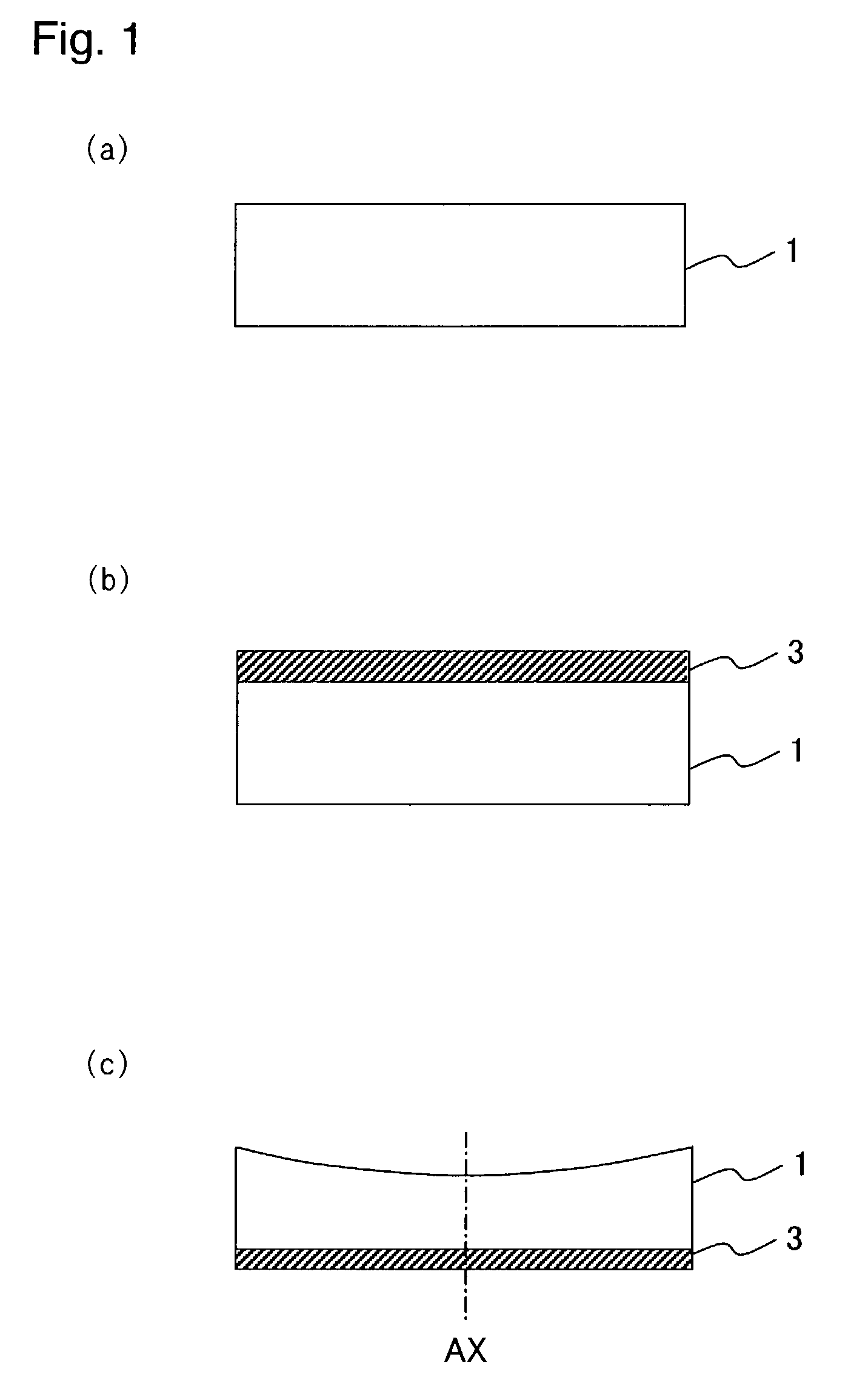
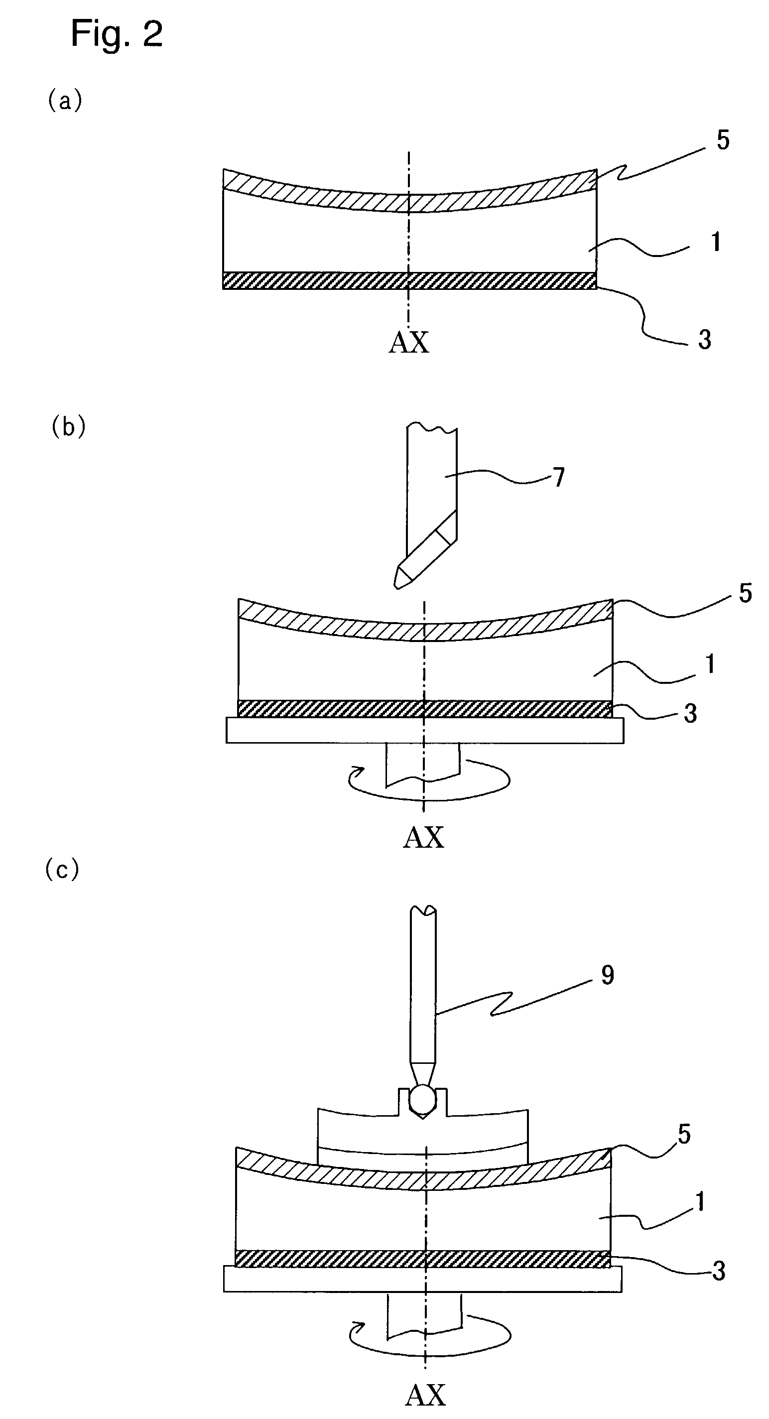
[0053]At first, as shown in FIG. 1(a), a disk-shaped metal plate (conductor plate) 1, which was composed of an aluminum alloy having a diameter of 150 mm and a thickness of 15 mm, was formed. One surface of the metal plate 1 was polished to be flat so that the flatness was about several to several tens of μm. A nickel film 3 was formed to have a thickness of about several tens of μm to several mm on the flat surface with the electroless plating method (FIG. 1(b)). Subsequently, the plated surface 3 was ground or cut by using a grinding machining machine or a cutting machining machine (not shown), and thus the plating thickness was made uniform. Subsequently, the surface, which was disposed on the side opposite to the surface having the nickel film 3 formed thereon, was machined to be a concave surface having a radius of curvature of 1800 mm by using a lathe (not shown) so that the thickness is thinnest at the central axis AX of the metal plate 1 (FIG. 1(c)). At this stage, the thick...

first modified embodiment

[0057]A modified embodiment of the first embodiment will be explained with reference to FIGS. 7(a) and 7(b). The first modified embodiment was constructed in the same manner as the first embodiment except that a base plate 20 was formed of a non-magnetic metal, recesses 18 each having a rectangular cross section were provided in the base plate 20, and magnets 21 for fixing the reflecting mirror elements 10 were embedded in the recesses 18. As shown in FIGS. 7(a) and 7(b), the base plate 20 was manufactured with a non-magnetic metal material composed of brass to have the same size as that in the first embodiment. The plurality of recesses 18 are formed in parallel in a predetermined direction on one surface of the base plate 20 by using an NC cutting machine (not shown) so that the cross section is rectangular with a length of 100 mm, a width of 3.0 mm, and a depth of 10 mm. Neodymium magnets 21, each of which had a thickness of 3.0 mm, were embedded in the respective recesses 18. Th...

second modified embodiment

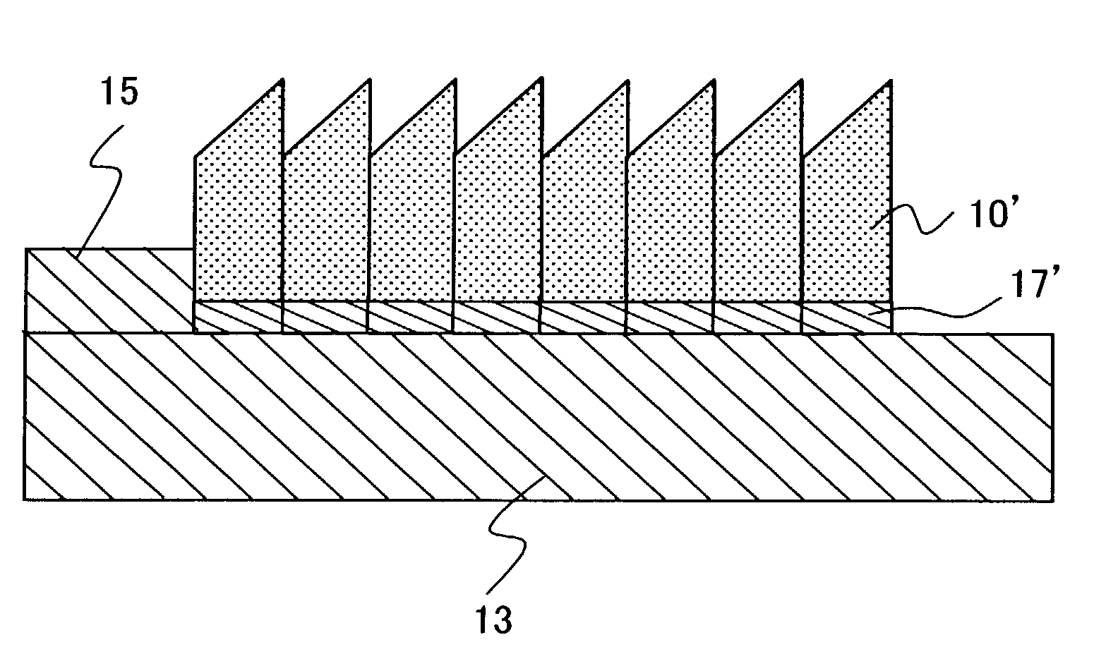
[0058]Another modified embodiment of the first embodiment will be explained with reference to FIG. 8. Reflecting mirror elements 10′ were constructed in the same manner as in the first embodiment except that silicon was used in place of the aluminum alloy as the material for the metal plate 1 and the nickel film 5 based on the electroless plating was not formed. One having a low resistance value (resistance value: 0.02 Ωm) was used as silicon. In this embodiment, the surface of the reflecting mirror element 10′ can be made into a mirror surface by polishing the surface of silicon by using an Oscar polishing machine. Therefore, it is unnecessary to perform the electroless plating step which would be otherwise performed in order to form the reflecting surface of the reflecting mirror element. It is possible to simplify the production steps for the reflecting mirror element.


PUM

PropertyMeasurementUnit
wavelengthaaaaaaaaaa
thicknessaaaaaaaaaa
diameteraaaaaaaaaa

Abstract

A multifaceted reflecting mirror is provided with a plurality of reflecting mirror elements 10 and a base plate 13 for magnet, each of the plurality of reflecting mirror elements 10 comprising a reflecting surface 19 and a magnetic film 17 formed on a bottom surface. The respective reflecting mirror elements 10 can be positioned highly accurately on the base plate 13 by using a positioning guide 15. The maintenance operation is easily performed as well, because the respective reflecting mirror elements 10 are detachable. When the multifaceted reflecting mirror is used in combination with another multifaceted reflecting mirror for an illumination optical system of a reflection type exposure apparatus which uses, as an exposure light beam, a light beam having a short wavelength such as soft X-ray, it is possible to illuminate an exposure area on a substrate with the light beam having an extremely uniform illumination intensity.

Description

CROSS-REFERENCE[0001]This application is a Continuation Application of International Application No. PCT / JP02 / 01614 which was filed on Feb. 22, 2002 claiming the conventional priority of Japanese patent Application Nos. 2001-047679 filed on Feb. 23, 2001 and 2001-047680 filed on Feb. 23, 2001.BACKGROUND OF THE INVENTION[0002]1. Field of the Invention[0003]The present invention relates to a multifaceted reflecting mirror comprising a plurality of reflecting mirror elements to be used for illuminating an object with a light beam having a uniform illuminance distribution, and a method for producing the multifaceted reflecting mirror. The present invention also relates to a reflection type illumination system to be used for illuminating an object with a light beam having a short wavelength of not more than 200 nm with a uniform illuminance distribution, and an exposure apparatus provided with the reflection type illumination system.[0004]2. Description of the Related Art[0005]At present...

Claims


Application Information

Patent Timeline
Patent Type & Authority Patents(United States)
IPC IPC(8): G02B5/08G02B7/182G02B5/09G02B26/08G03F7/20G21K1/06
CPCG02B5/08G02B5/09G02B7/182G02B26/085G03F7/702G03F7/70958G03F7/70975G21K1/06G03F7/70141G02B7/1828Y10S359/903
Inventor TAKINO, HIDEO
Owner NIKON CORP
Why Eureka
Try Eureka