Solid-state devices with radial dopant valence profile

a solid-state device and valence profile technology, applied in the direction of active medium shape and construction, laser details, active medium materials, etc., can solve the problems of low production yield, low production yield, and variations in lasing threshold and efficiency, so as to improve mode discrimination, improve brightness output, and reduce beam divergence

Inactive Publication Date: 2006-02-07
HRL LAB
View PDF22 Cites 14 Cited by
  • Summary
  • Abstract
  • Description
  • Claims
  • Application Information

AI Technical Summary

Benefits of technology

[0018]For Q-switches, the dopant and valence states are selected to create a radial variation in the optical density of the material at the lasing wavelength. For laser pump cavities, the dopant and valence states are selected to create a radial variation in the net gain of the lasing medium. The present invention offers improved mode discrimination within a laser resonator, and results in a lower beam divergence and higher brightness output.
[0019]In an illustrative Q-switch implementation of the present teachings, a solid-state material, such as a yttrium aluminum garnet (YAG) crystal rod, is doped with trivalent chromium ions (Cr3+). The material, disposed in the rod, is subjected to an oxidizing atmosphere at elevated temperature in a post-fabrication process that converts the trivalent chromium ions near the periphery of the rod's cylindrical surface to the tetravalent state (Cr4+). The rod is then cut into disks which have a radially-dependent distribution of valence states with the highest density of tetravalent states near the periphery and lowest at the center. The trivalent chromium ions are essentially transparent to 1.064 micrometer radiation from a Nd:YAG laser. The tetravalent ions, however, absorb at this wavelength on a transition that bleaches (becomes transparent) at high laser radiation intensities. When inserted into a Nd:YAG laser cavity, the disk acts as a saturable absorber Q-switch that bleaches first in the center and provides a higher optical density toward the periphery, thereby discriminating against the larger (higher order) transverse modes within the laser resonator. The result is that the lower order modes prevail and yield a higher beam quality (lower beam divergence and higher brightness). An additional advantage is that the invention also serves as a soft apodizing aperture to “gracefully” provide mode discrimination without any hard edges that would otherwise create deleterious diffraction effects.
[0020]The fabrication apparatus is straightforward, relatively inexpensive and can be implemented as part of a crystal or glass fabrication process. The finished product is in a configuration suitable for numerous applications, including very small resonators. High product quality is readily achieved with standard manufacturing processes. Furthermore, the fact that the saturable absorption is due to a substitutionally doped ionic species (as opposed to a radiation-damage-induced color-center defect) means that the present invention is much more stable against light exposure and temperature. This stability feature is an important benefit for many military and industrial laser applications.

Problems solved by technology

Unfortunately, color center Q-switches have several shortcomings including (1) the need for an expensive 1–2 MeV electron irradiation source for fabrication (and possibly a Cobalt-60 source of gamma radiation to provide a background level of color centers), (2) a relatively long crystal, which is expensive and not generally suitable for small laser cavities of the type used in miniature, eye safe laser rangefinders, (3) relatively poor control of optical density resulting in variations in lasing threshold and efficiency and requiring selection of suitable devices (low production yield).
Also, F2− color centers are quite photosensitive and will disappear under weak UV exposure [see W. Gellermann et al, J. Appl. Phys. 61, 1297–1303 (1987)], and the color centers are somewhat temperature sensitive making them non-ideal for fielded applications.
Thus, when such a crystal is side-pumped, non-uniform absorption and thus non-uniform gain often result, with the highest gain being near the edge of the lasing medium.
The chamfer will shadow or block the laser light, and since the highest gain is at the edges of the crystal, inefficient lasing results.
End pumping requires expensive high-brightness pump diodes and durable, difficult-to-produce dichroic coatings since the pumping and laser light extraction take place through the same optical surfaces (i.e. the ends of the rod) while requiring quite different reflectivity characteristics.
This process adds significant cost and cycle time to the manufacture of solid-state lasers and is therefore undesirable, particularly in the cost-driven eye safe laser rangefinder market for individual soldier weapon fire control systems.

Method used


Image

  • Solid-state devices with radial dopant valence profile
  • Solid-state devices with radial dopant valence profile
  • Solid-state devices with radial dopant valence profile

Examples


Embodiment Construction

[0034]While the present invention is described herein with reference to illustrative embodiments for particular applications, it should be understood that the invention is not limited thereto. Those having ordinary skill in the art and access to the teachings provided herein will recognize additional modifications, applications, and embodiments within the scope thereof and additional fields in which the present invention would be of significant utility.

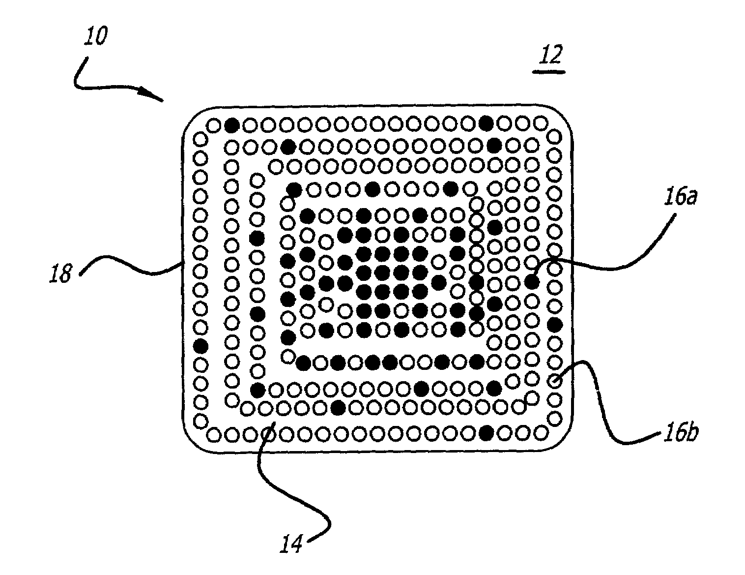
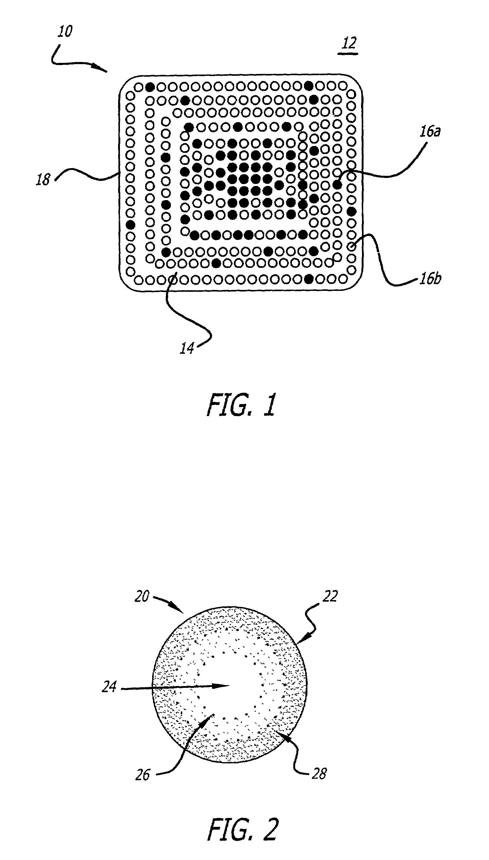
[0035]FIG. 1 is a cross-section of a generic, solid state, laser light control device fabricated in accordance with the teachings of the present invention. The device 10 consists essentially of a solid-state host material 14 which contains: a dopant species 16 at a first valence state ‘a’, the concentration of which increases with distance from the surface 18; and the same dopant species 16 at a second valence state ‘b’, the concentration which decreases with distance from the surface 18. This device 10 is produced by exposing the sol...


PUM


Abstract

A solid state, laser light control device (20, 30) and material (10), and methods of producing same. The device (20, 30) and material (10) consist essentially of a host material (14) which contains: a dopant species (16) at a first valence state (a), the concentration of which increases with distance from the surface (18); and the same dopant species (16) at a second valence state (b), the concentration which decreases with distance from the surface (18). The method comprises the steps of: obtaining a doped solid state material (14); exposing the solid state material (14) to elevated temperature, for a period of time, in an oxidizing or reducing atmosphere. The elevated temperature and time of exposure are selected to change the valence state (a) of the dopant (16) in direct proportion to distance from the surface (18) of the solid state material (16). What is thereby produced is a solid state device (20, 30) in which the concentration of the dopant 16 at the second valence state (b) decreases with radius, the concentration of the dopant (16) at the first valence state (a) increases with radius, and the sum of these concentrations remains constant.

Description

BACKGROUND OF THE INVENTION[0001]1. Field of Invention[0002]The present invention relates to fabrication of Q-switches and laser pump cavities. Specifically this invention relates to solid state devices having a radially dependent dopant valence state density.[0003]2. Description of the Related Art[0004]A laser is a device which produces a beam of coherent light. In a typical laser, an incoherent light source imparts energy to a lasing medium, which produces light in which the waves are in phase, termed coherent light, through particular electron transitions. Where the lasing medium is properly designed, the coherent light is emitted as a beam. In certain cases, it is desirable that the emitted beam of coherent light be more intense than naturally occurs from the lasing medium, and a type of laser termed a Q-switched, pulsed laser has been developed for this purpose.[0005]The pulsed laser contains a light controller termed a Q-switch which limits the buildup of light reflecting back...

Claims


Application Information

Patent Timeline
Patent Type & Authority Patents(United States)
IPC IPC(8): H01S3/11H01S3/16H01S3/06H01S3/113
CPCH01S3/113H01S3/061H01S3/0617H01S3/094084H01S3/1681H01S3/1623H01S3/1643H01S3/0941
Inventor BYREN, ROBERT W.SUMIDA, DAVID S.
Owner HRL LAB
Why Eureka
Try Eureka