Liquid crystal panel and liquid crystal projector

a liquid crystal panel and projector technology, applied in the field of liquid crystal panel and liquid crystal projector, can solve the problems of heat generation, low light usage efficiency, single plate type inferior to three-plate type in picture quality, etc., and achieve high picture quality, high brightness, and high fineness.

Inactive Publication Date: 2006-02-21
SEMICON ENERGY LAB CO LTD +1
View PDF17 Cites 25 Cited by
  • Summary
  • Abstract
  • Description
  • Claims
  • Application Information

AI Technical Summary

Benefits of technology

[0054]In view of the foregoing problems, an object of the present invention is to provide a liquid crystal projector which is made thin and lightweight, and at the same time, which is made to have high fineness, high picture quality, and high brightness. Another ob...

Problems solved by technology

However, in the case where the same liquid crystal panel is used in the three-plate type and a conventional single plate type, while three colors are overlapped with each other on one pixel in the three-plate type, the single plate type can merely use one pixel as a pixel of one color, so that the single plate type is inferior to the three-plate type in picture quality.
Thus, only ⅓ of white light incident into the liquid crystal panel is transmitted, and usage efficiency of light is low.
For the purpose of improving the brightness of the single plate type liquid crystal projector, although a method of making the light source bright has been adopted, there have occurred problems of heat generation due to light absorption of a color filter and light resistance.
It is difficult to reduce the thin film transistor (pixel TFT) for driving a liquid crystal and the wiring at the same scale as a reduction in the pixel pitch.
If the thin film transistor is made excessively small, the amount of flowing current is limited.
Thus, if the pixel TFT is excessively small, it becomes difficult to cause a current necessary for driving the liquid crystal to flow.
Besides, if the wiring is made excessively, thin, the resistance of the wiring becomes large.
However, if the brightness of the light source is raised, consumed electric power becomes large, which is not preferable.
The former is not easy in design and manufacture, and it is difficult to increase the number (integration) of microlenses per unit area of the microlens array.
However, if the radius of curvature r is made small, the focal depth becomes shallow, and it becomes difficult to effectively condense light to the opening portion of the pixel.
Thus, in the case where a cell gap is irregular over the whole substrate, even if there is no problem when the diameter D of the microlens is large, there has been a problem that uneven brightness of an image is seen when the diameter D is made small.
Further, in the case where therma...

Method used


Image

  • Liquid crystal panel and liquid crystal projector
  • Liquid crystal panel and liquid crystal projector
  • Liquid crystal panel and liquid crystal projector

Examples


embodiment 1

[0256]In this embodiment, a method of fabricating gap holding members on a TFT substrate will be described with reference to FIGS. 9A to 9D.

[0257]FIG. 9A shows a state in which a pixel portion (not shown) has been formed on a TFT substrate 901, an orientation film 902 has been formed on the pixel portion, and a rubbing treatment has been carried out to the orientation film 902.

[0258]An insulating coating material which becomes gap holding members is applied onto the orientation film 902, so that an insulating coating 903 is formed. As the insulating coating material, a resin material having a specific gravity and thermal expansion coefficient close to a liquid crystal is preferable. For example, it is possible to use a resin material selected from the group consisting of polyimide, acryl, polyamide, polyimidoamide, and epoxy resin. Besides, it is possible to use an ultraviolet ray curing resin or thermosetting resin material which can be formed without exerting a large thermal influ...

embodiment 2

[0266]In this embodiment, a three-plate type liquid crystal projector different from the liquid crystal projector discussed in the embodiment mode of the present invention will be described.

[0267]Reference will be made to FIG. 10. FIG. 10 is a structural view of an optical system of this three-plate type liquid crystal projector. Reference numeral 2401 designates a white light source made of a lamp and a reflector. White light having a spectrum of red, green and blue is emitted from the light source 2401. The light source 2401 is set so that the parallelism of the emitted white light becomes high. Besides, the reflector is used to effectively use the white light emitted from the lamp.

[0268]The white light emitted from the light source 2401 enter dichroic mirrors 2402 and 2403. These two dichroic mirrors 2402 and 2403 split the white light from the light source 2401 into lights (red, green, blue) of the three primary colors.

[0269]One of the lights of blue, red and green split by the ...

embodiment 3

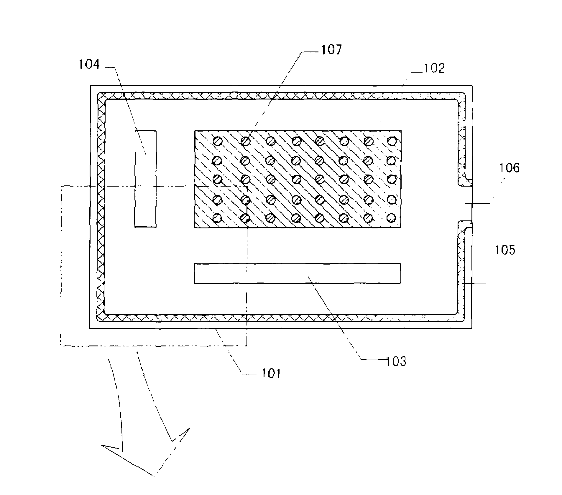
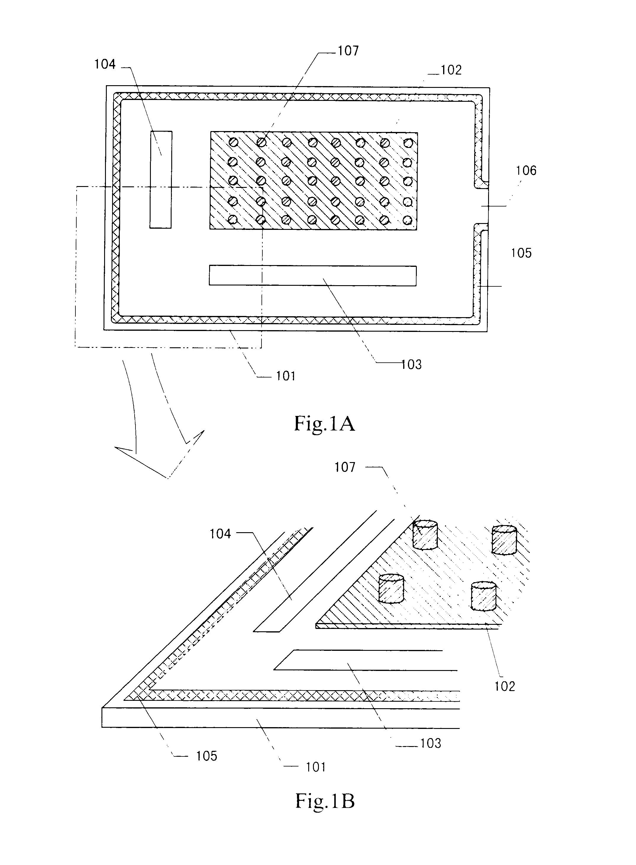
[0272]In this embodiment, the arrangement of gap holding members different from that shown in FIG. 1 will be described.

[0273]FIG. 11A is a schematic view of a TFT substrate of a liquid crystal panel included in a liquid crystal projector of the present invention. A source signal line driving circuit 1103, a gate signal line driving circuit 1104, and a pixel portion 1102 are provided on a TFT substrate 1101 as shown in FIG. 11A. A seal member 1105 is provided at the periphery of the TFT substrate 1101 and a liquid crystal is injected through a liquid crystal injection port 1107. Gap holding members 1106 are provided on the whole surface of the TFT substrate 1101.

[0274]Since the gap holding member is an insulator, if the gap holding member is provided on a driving circuit including the source signal line driving circuit and the gate signal line driving circuit, a capacitance is formed and the operation of the driving circuit becomes slow.

[0275]However, in this case, as compared with t...


PUM

PropertyMeasurementUnit
Sizeaaaaaaaaaa
Shapeaaaaaaaaaa
Light intensityaaaaaaaaaa

Abstract

There is provided a liquid crystal panel in which the brightness of an image is high, and deterioration in display quality due to defects such as uneven display or uneven brightness is suppressed. The liquid crystal panel includes a pixel portion including a plurality of thin film transistors and pixel electrodes formed on a first substrate, a second substrate, a liquid crystal and gap holding members provided between the first substrate and the second substrate, and a microlens array including a plurality of microlenses and provided on a surface of the second substrate, the surface being opposite to the first substrate.

Description

BACKGROUND OF THE INVENTION[0001]1. Field of the Invention[0002]The present invention relates to a liquid crystal panel and a liquid crystal projector using the liquid crystal panel.[0003]2. Description of the Related Art[0004]In recent years, a technique for fabricating a semiconductor device in which a semiconductor thin film is formed on an inexpensive glass substrate, such as a thin film transistor (TFT), has been rapidly developed. The reason is that demand for an active matrix type liquid crystal panel has risen.[0005]The active matrix type liquid crystal panel (liquid crystal panel) is such that a thin film transistor (pixel TFT) is disposed for each of several tens to several million pixel portions disposed in matrix form and an electric charge going in and out of each pixel electrode is controlled by a switching function of the pixel TFT.[0006]Besides, particularly, a projection type display device using a liquid crystal panel, a so-called projector has rapidly increased it...

Claims


Application Information

Patent Timeline
IPC IPC(8): G02F1/1339
CPCG02F1/133526G02F1/13394H04N9/3105G02F2202/023G02F1/1368
Inventor YAMAZAKI, SHUNPEIKOYAMA, JUNTAMAI, KAZUHIKOTAKAFUJI, YUTAKA
Owner SEMICON ENERGY LAB CO LTD
Why Eureka
Try Eureka