
Biopolymer array scanner with real-time saturation detection

a biopolymer array and scanner technology, applied in the field of biopolymer array optical scanners, can solve the problems of failure to collect weak signal information, user may not know often has little idea of the brightness of the fluorescence that will be emitted by a particular sample, etc., to achieve shorten the time-to-results, improve the scanning efficiency, and improve the scanning efficiency

Inactive Publication Date: 2006-03-14
AGILENT TECH INC
View PDF17 Cites 10 Cited by
  • Summary
  • Abstract
  • Description
  • Claims
  • Application Information

AI Technical Summary

Benefits of technology

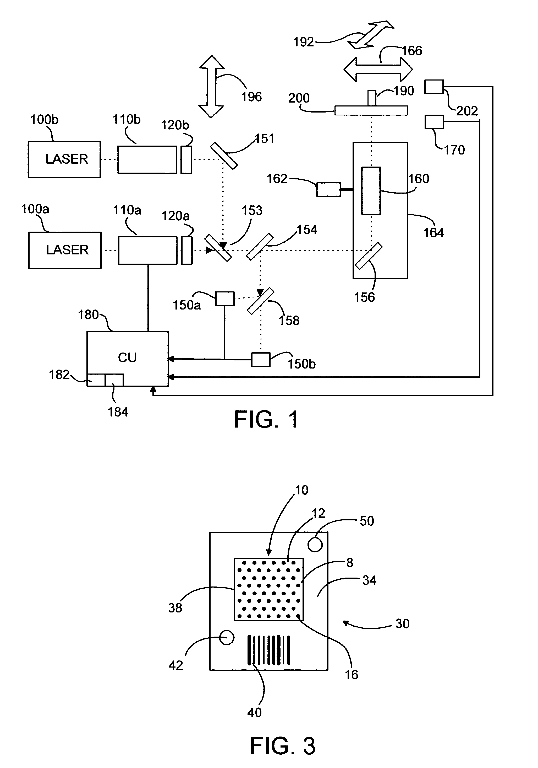
The present invention is about methods for gathering feature saturation data while scanning an array and using it for improved scanning. This is different from previous techniques that require post-processing of scan data, which causes delays. The invention allows for faster results and higher scanner throughput by adjusting the scanner after the first scan and using the saturation data for calibration or to protect the detector. The invention also includes methods for handling and storing saturation-related information for later interpretation of the scan data. The technical effects of the invention include improved scanning efficiency and accuracy.

Problems solved by technology

However, a user often has little idea of the brightness of the fluorescence that will be emitted by a particular sample.
Likewise, the user will not know how high or low to set the gain of a detector that collects emitted fluorescence and produces a corresponding data signal.
Setting laser power and / or detector sensitivity too low may result in failure to collect weak signal information.
Accordingly, manual adjustment of these components is time consuming.
With the other lines, however, the same problems encountered with manual scanning and tuning optical system attenuation or excitation system gain from photo-bleaching as a result of rescanning are encountered.
The risk of damage to the sample is further increased when multiple channels are used.

Method used


Image

  • Biopolymer array scanner with real-time saturation detection
  • Biopolymer array scanner with real-time saturation detection

Examples


example

[0082]In connection with an Agilent model G2565AA or G2565BAscanner running software according to the present invention, an “image file” it outputs may be employed to store saturation data. For example, one can take the “n” highest numbers representing pixel intensity data and reserve them to store saturation information. In such an approach, where pixel results are expressed in terms of 216−1 or 16 bits, a saturated pixel may be represented by a value of up to 65535 (corresponding to a value 10-fold over saturation level), 65534 (corresponding to a value 9-fold over saturation level), . . . 65527 (corresponding to a value 2-fold over saturation level), etc. In the instance noted above where saturation is detected in connection with adjacent dimmer pixels, these pixels may be used to store saturation data using the lowest “n” numbers. Stored thus, it takes a reduction of the data range by less that 1% to store saturation factors up to 5-fold with an error of 1% or less. Larger porti...


PUM

PropertyMeasurementUnit
areaaaaaaaaaaa
areaaaaaaaaaaa
diameteraaaaaaaaaa

Abstract

Optical scanner system approaches are described in which signal saturation data is produced in real-time. The data generated may be used for tuning a subsequent scan, in protection of optical detector components from damage or otherwise. Approaches for obtaining and storing or expressing the data are also disclosed. Also provided are methods of using the subject system is biopolymer array based application, including genomic and proteomic applications.

Description

FIELD OF THE INVENTION[0001]This invention relates to biopolymer array optical scanners.BACKGROUND OF THE INVENTION[0002]Pharmaceutical, biotechnology, or genomics companies use DNA analysis systems for target identification and drug screening in pharmaceutical drug discovery. In many of these systems, biomolecules (e.g., DNA, RNA, cDNA, proteins) labeled with various dyes bind to chips that offer different molecular probe counterparts for binding in different locations of the chip. A scanner is then used to read the fluorescence of these resultant surface bound molecules under illumination with suitable (most often laser) light. The scanner acts like a large field fluorescence microscope in which the fluorescent pattern caused by binding of labeled molecules is scanned on the chip. In particular, a laser induced fluorescence scanner provides for analyzing large numbers of different target molecules of interest, e.g., genes / mutations / alleles, in a biological sample.[0003]The scannin...

Claims


Application Information

Patent Timeline
Patent Type & Authority Patents(United States)
IPC IPC(8): G01N33/50C12Q1/68G01N33/48G06G7/00G01N21/25G01N21/64
CPCG01N21/6452G01N21/6456C12Q1/6837G01N2021/6421G01N2021/6419
Inventor DORSEL, ANDREAS N.MCMILLAN, JEFFREY M.
Owner AGILENT TECH INC
Learn More