Transparent protective layer for a body

a protective layer and transparent technology, applied in the field of transparent protective layer, can solve the problems of high risk of surface damage formation, traces of use produced on the hob, formation of scratches on the surface, etc., and achieve the effects of high thermal stability, attractive visual appearance and transparency, and high resistance to scratching

Inactive Publication Date: 2006-03-28
SCHOTT AG
View PDF15 Cites 41 Cited by
  • Summary
  • Abstract
  • Description
  • Claims
  • Application Information

AI Technical Summary

Benefits of technology

[0048]The protective layers according to the invention are suitable for coating a very wide range of bodies which in particular need to have a high resistance to scratching and a high thermal stability. Furthermore, they allow an attractive visual appearance and transparency to be achieved. They are particularly suitable for use as protective layers for glass, glass-ceramic or bodies formed from other non-metallic, crystalline materials, without being restricted to these specific applications. It is thus also possible to coat plastic bodies, for example in order to improve the surface quality and barrier properties of plastics containers.
[0049]The protective layer is particularly advantageously suitable for the coating of glass-ceramic cooking plates. A high resistance to scratching, a high thermal stability and a visually attractive appearance are crucial requirements for this application which can be fulfilled by the coating according to the invention.

Problems solved by technology

Everyday use, for example the cookware being put down and moved around, and the cooking plates being cleaned with abrasive cleaning agents and sponges or with a scraper, imposes a high mechanical loading on the cooking hob, which can lead to traces of use being produced on the hob.
In particular in this state, there is a high risk of surface damage forming, for example through damage caused by rough bases of ceramic objects.
All the surface damage incurred, over the course of time, leads to the formation of scratches on the surface, which are more or less noticeable to the user depending on the selected illumination.
An additional factor is that damage to the surface offers points of attack for soiling.
The ease of cleaning of the surface becomes restricted, since it is much more difficult to clean dirt out of this damage.
However, over the course of time, the surfaces of glass-ceramic plates have become smoother and shinier, which for the reasons mentioned above leads to an increased susceptibility to scratching.
Although this protective layer in principle increases the mechanical load-bearing capacity of the glass-ceramic cooking plates, so that, when the cooking plate is in use the susceptibility to scratches can be reduced compared to an unprotected cooking plate, the enamel fluxes or silicate protective layers which are all that is disclosed by the EP document still do not offer optimum long-term mechanical protection.
Specifically, one drawback is that the protective layer itself represents a décor which is applied by means of screen printing.
The minimum dimension of décors of this type is of the order of magnitude of 0.5 mm, which is in any event visually perceptible and therefore interferes with the design, in particular if glasses or glass-ceramics with smooth surfaces are desired.
Furthermore, the explanations given do not allow any conclusions to be drawn as to the extent to which the proposed solution is compatible with the heater systems used.
In particular the use of preferably dark materials as protective layer for glass-ceramics with a high IR transparency and radiant heaters will lead to restrictions in terms of the desired IR transparency and therefore to losses in terms of the initial cooking performance.
One drawback is the high cost of the process, in particular if large-area coatings have to be applied homogeneously.
Hitherto, inhomogeneities have been inevitable, and this moreover has a long-term adverse effect on the visual appearance.
One drawback in this context is that such thick layers are very rough, and therefore the use properties, such as the abrasion caused by pots and pans, manual abrasion and the cleaning properties are adversely affected.
The hard-material layers described here are suitable for applications in the room temperature range, but their properties change at high temperatures, as are customary, for example, in the case of cooking plates, making them unsuitable for use at high temperatures.
After prolonged use in the hot areas, or in the event of maximum thermal loading, layers of this type may undergo disadvantageous changes.
The roughening alone may be optically perceptible, and the recesses which form additionally make cleaning more difficult.
The problem of crystallization in the hot areas is exacerbated by mechanical failure of the scratchproof layer.
During crystallization, the structure of the layer changes, with the result that cracks are formed in the layer.
The loss of lateral cohesion means that the layer no longer offers any particular protection against scratching.
However, a layer of this type, produced using the known processes, has a low density, which means that a layer of this type is porous.
In addition to entailing very high process costs, crystalline layers of this type still have a rough surface.
However, on account of their coarse crystalline structures, the layers described in this document have a high roughness or porosity.
Rough and porous surfaces quickly become dirty and are difficult to clean.
Moreover, they are not visually clear and transparent, but rather are highly diffractive and are unsuitable for applications with visually attractive surfaces.

Method used


Image

  • Transparent protective layer for a body
  • Transparent protective layer for a body
  • Transparent protective layer for a body

Examples


Embodiment Construction

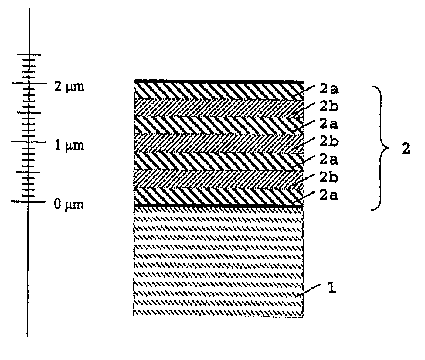
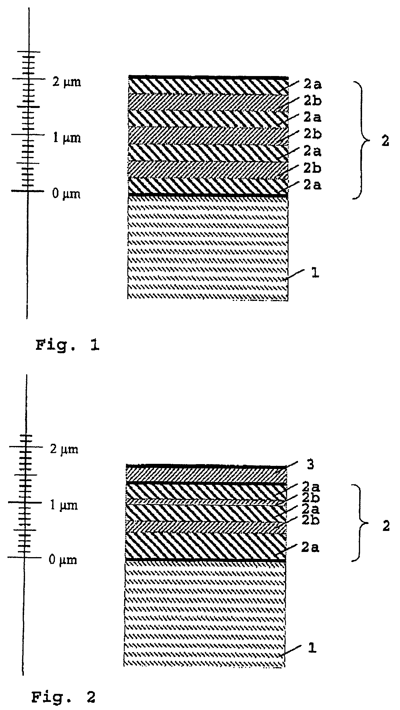
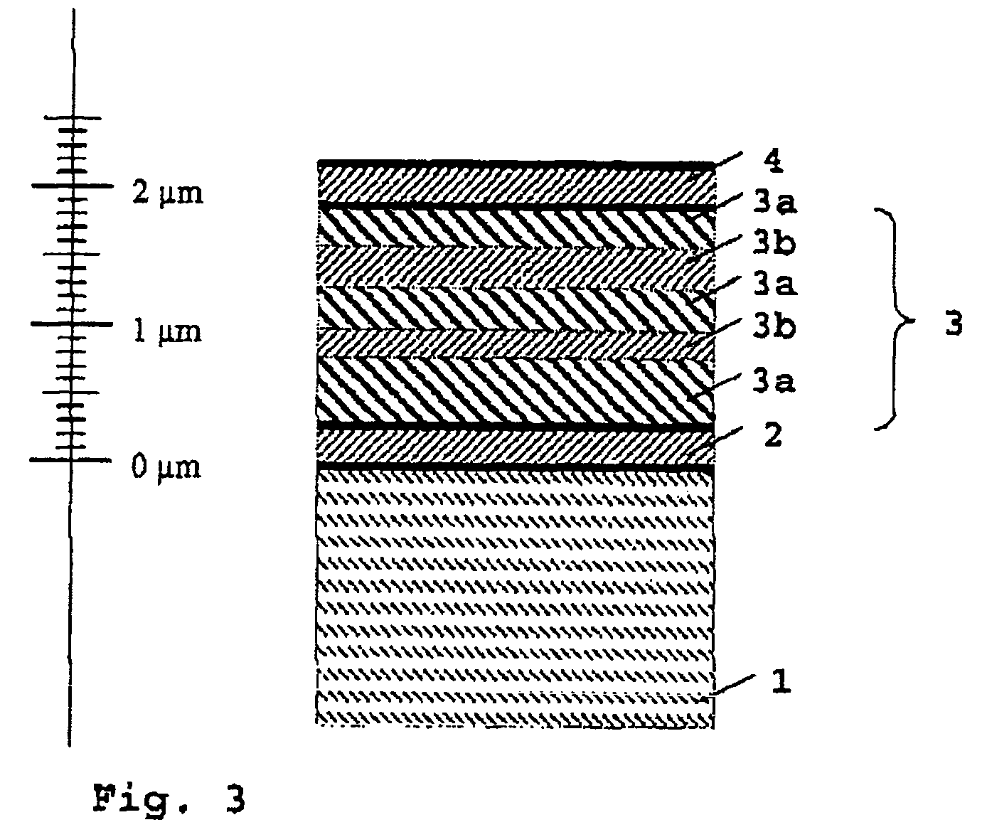
[0056]FIGS. 1 to 3 diagrammatically depict possible variants of protective layers according to the invention for coating substrates (1). The invention is not restricted to these which cannot all be explained in detail.

[0057]In FIG. 1, a substrate (1) is coated with a hard-material layer (2). The hard-material layer (2) has three interlayers (2b) formed from amorphous titanium / aluminum oxide. The interlayers (2b) are arranged between four sublayers (2a) formed from crystalline, yttrium-stabilized zirconium oxide. The layer thickness of the interlayers (2b) and sublayers (2a) is in each case 300 nm, and the total layer thickness of the hard-material layer (2) is 2100 nm.

[0058]In FIG. 2, a substrate (1) is coated with two hard-material layers (2, 3). The first hard-material layer (2) includes two interlayers (2b) formed from amorphous titanium / aluminum oxide, the interlayer (2b) having different layer thicknesses (200 nm and 100 nm). The interlayers (2b) are arranged between three subl...


PUM

PropertyMeasurementUnit
thicknessaaaaaaaaaa
thicknessaaaaaaaaaa
Raaaaaaaaaaa

Abstract

The invention relates to a transparent protective layer, in particular a scratchproof layer for glass and glass-ceramic, which is able to withstand high temperatures, has a smooth and dense surface, an attractive surface design and is preferably used for coating cooking plates. A protective layer according to the invention comprises at least one crystalline metal oxide layer which has at least one interlayer formed from an amorphous, thermally stable mixed oxide, the interlayer being arranged being sublayers of the metal oxide layer. A further protective layer according to the invention comprises at least one amorphous, thermally stable mixed oxide layer which has at least one interlayer formed from a crystalline metal oxide, the interlayer being arranged between the sublayers of the amorphous mixed oxide layer. The amorphous mixed oxide layer has at least two metallic components. The crystalline metal oxide layers preferably consist of yttrium-stabilized zirconium oxide, and the amorphous mixed oxide layers preferably consist of titanium/aluminum oxide.

Description

CROSS REFERENCE TO RELATED PATENT APPLICATIONS[0001]This patent application claims priority to German Patent Application No.: DE 103 42 397.4-45 filed on Sep. 13, 2003.BACKGROUND OF THE INVENTION[0002]1. Field of the Invention[0003]The invention relates to a transparent protective layer, in particular to a transparent hard-material layer with a high resistance to scratching and a high thermal stability.[0004]The invention relates specifically to a protective layer for glass-ceramic plates, and to a process and apparatus for coating them, these glass-ceramic plates preferably being used as cooking plates in cooking hobs and having a protective layer with a higher scratch resistance than the uncoated glass-ceramic on at least one side.[0005]2. Description of Related Art[0006]Modern cooking hobs have a glass-ceramic plate as the cooking plate, the glass-ceramic plate typically being planar, although it may also be deformed in two or three dimensions. Glass-ceramic plates are both known...

Claims


Application Information

Patent Timeline
Patent Type & Authority Patents(United States)
IPC IPC(8): B32B19/00H05B6/12B32B9/00C03C17/34F24C15/10
CPCC03C17/3417C03C17/3435Y10T428/24942
Inventor DZICK, JURGEN
Owner SCHOTT AG
Why Eureka
Try Eureka