Analogue amplifier with multiplexing capability

a technology of analog amplifiers and multiplexers, applied in gated amplifiers, instruments, electric devices, etc., can solve the problems of unreliable circuit features, new failure mechanisms emerge, and the impact of new failure mechanisms

Active Publication Date: 2006-04-11
INFINEON TECH AG
View PDF10 Cites 6 Cited by
  • Summary
  • Abstract
  • Description
  • Claims
  • Application Information

AI Technical Summary

Benefits of technology

[0013]Accordingly it is the object of the present invention to provide means which allow a better testability by increasing internal controllability.
[0014]Further advantages of the present invention are that the redesign effort is minimal, that the silicon area overhead is minimal and that the increase of the power supply current consumption is minimal.
[0015]The basic idea of the present invention is that in the main signal propagation path of analogue integrated circuits a number of amplifiers are provided to drive proper internal nodes in order and to guarantee the required signal to noise ratio. Whenever a controllability issue is detected the design of some amplifier is modified to include multiplexing capabilities that allow injecting test signals within the main signal propagation path with minimal redesign effort and minimal impact upon normal operation mode of the required amplification function.

Problems solved by technology

On the other hand, new technologies make more and more defects to be non-visible, new failure mechanisms emerge and a relevant number of circuit features are unsimulatable.
As a consequence, test cost and complexity increases, but also a higher risk exist to produce delays in bringing products to market or just to suffer from yield detractors that lead to higher manufacturing cost.
However, because of the ad-hoc nature of the task, top level floor plan layout constrains may lead to situations where it is not possible to include new multiplexor blocks in the original design without severe impact upon schedule because of the re-design effort due.
The drawback of a multiplexor-based solution is that the load capacitance is increased.
Further providing a multiplexor increases the necessary area on the chip such increasing production costs.
A further drawback is that because of the additional multiplexor the power consumption is increased.

Method used


Image

  • Analogue amplifier with multiplexing capability
  • Analogue amplifier with multiplexing capability
  • Analogue amplifier with multiplexing capability

Examples


Embodiment Construction

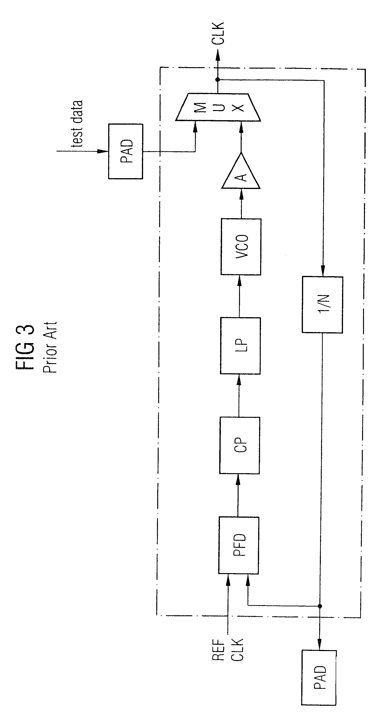
[0032]FIG. 3 shows a conventional approach for testing a phase locked loop, (pLL), circuit within mixed signal circuits. A phase locked loop is a system with induced feedback to maintain an output signal in a specific phase relationship with a reference signal. The pll-circuit shown in FIG. 3 comprises of phase frequency detector PFD controlling a charge pump CP which supplies a deviation signal to the low pass filter LP. The filtered signal is supplied to a voltage controlled oscillator VCO. The voltage controlled oscillator VCO is a circuit that produces an AC-output signal whose frequency is proportional to the input control voltage. The VCO output signal is amplified by a conventional amplifier as shown in FIG. 4. For test purposes a multiplexor is provided at the output of the amplifier in the conventional approach as shown in FIG. 3. In the feedback loop a division circuit is provided which produces an output signal whose frequency is an integer division of the input signal fr...


PUM

PropertyMeasurementUnit
voltageaaaaaaaaaa
biasing voltageaaaaaaaaaa
negative biasing voltageaaaaaaaaaa

Abstract

An analogue amplifier with multiplexing capability, without the need to incorporate a multiplexor, comprising an input port, a test input port, an output port, a control input to switch the amplifier between a normal amplifying mode and a test mode, wherein a analogue signal introduced to the input port is amplified to the output port in normal mode, and a test signal on the test port is routed to the output port when the amplifier is in test mode.

Description

FIELD OF THE INVENTION[0001]The invention refers to an analogue amplifier to increase circuit testability by featuring additional multiplexing capability.DESCRIPTION OF PRIOR ART[0002]Any procedure carried out upon an integrated circuit intended to establish its quality, performance or reliability is commonly called testing.[0003]Testing can be carried out at different stages during the development of an integrated circuit; different procedures are followed, according to particular goals and circuit type, for each development stage.[0004]The degree to which an integrated circuit facilitates the establishment of test criteria and the performance of tests to determine whether those criteria have been met is commonly referred as testability.[0005]According to existing literature, integrated circuits testability can be quantified by means of existing capacity to control and or to observe voltages on relevant nodes in the integrated circuit. These magnitudes are commonly referred as cont...

Claims


Application Information

Patent Timeline
Patent Type & Authority Patents(United States)
IPC IPC(8): G01R19/00G01R21/00G01R23/00G01R31/26H03F3/72
CPCH03F3/72H03F2200/417E04G9/05E04G9/06
Inventor ARGUELLES, JAVIER
Owner INFINEON TECH AG
Why Eureka
Try Eureka