
Grating sensor

Active Publication Date: 2006-04-11
VERIDIAN SYST
View PDF61 Cites 40 Cited by
  • Summary
  • Abstract
  • Description
  • Claims
  • Application Information

AI Technical Summary

Benefits of technology

[0008]The analyte recognition material may be an antibody, nucleic acid, lectin or other substance. The sample may be obtained from a mammal, including a human, plant, or the environment. A positioning system may be provided for mo

Problems solved by technology

Biological weapons, infectious diseases, and environmental pathogens threaten both military and civilian personnel.
Current technology lacks the capability to accurately detect the presence of trace amounts of chemical and biological warfare agents quickly and reliably.
This requirement includes additional steps and expense to the detection process, a significant disadvantage when prompt detection is necessary.
Waveguide sensors typically have the disadvantages of high sensitivity to changes in the ambient conditions such as temperature, resulting in undesirable signal to noise ratios.
However, intensity (irradiance) measurements are not sensitive enough for many applications and are sensitive to noise, resulting in difficulty in relating and quantifying the changes in the detected diffraction irradiance signal to an input stimulus.

Method used


Image

  • Grating sensor
  • Grating sensor
  • Grating sensor

Examples


example 1

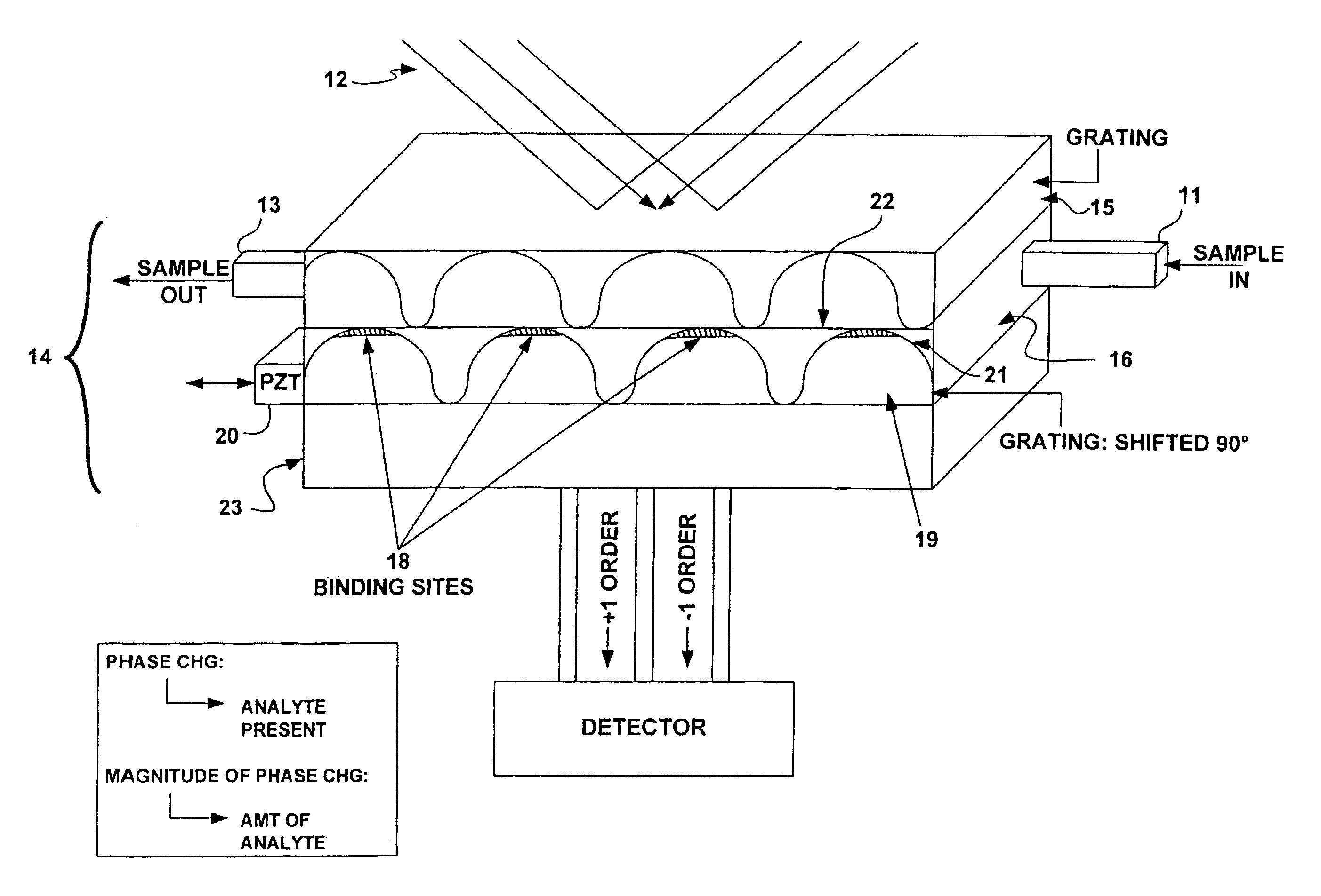
[0088]FIGS. 5A and 5B illustrate a detailed view of a grating. Molecular receptors, such as antibodies, are placed in precise locations on an optical substrate. In this case, the antibody receptors lie in 2 μm wide lines 30 with 2 μm wide separations 32 (a 4 um period) and are placed on a substrate 34 made of fused silica. This 4 um period will produce 1st order diffraction angle of ˜9 degrees at a wavelength of 633 nm. Blocking material 36 to prevent non-specific binding of receptors and analyte may be placed in the region between the lines. Upon introduction of buffer solution putatively containing the antigen corresponding to the chosen antibody, specific binding between immobilized antibody 38 and analyte 40 occurs at precise locations, i.e. at the peaks of the grating. This molecular binding changes the physical and optical height [(index)×(change in height)] of the grating. In this example, the heights of the antibody (hab)+antigen (hag) layers are expected to be in the 10's o...

example 2

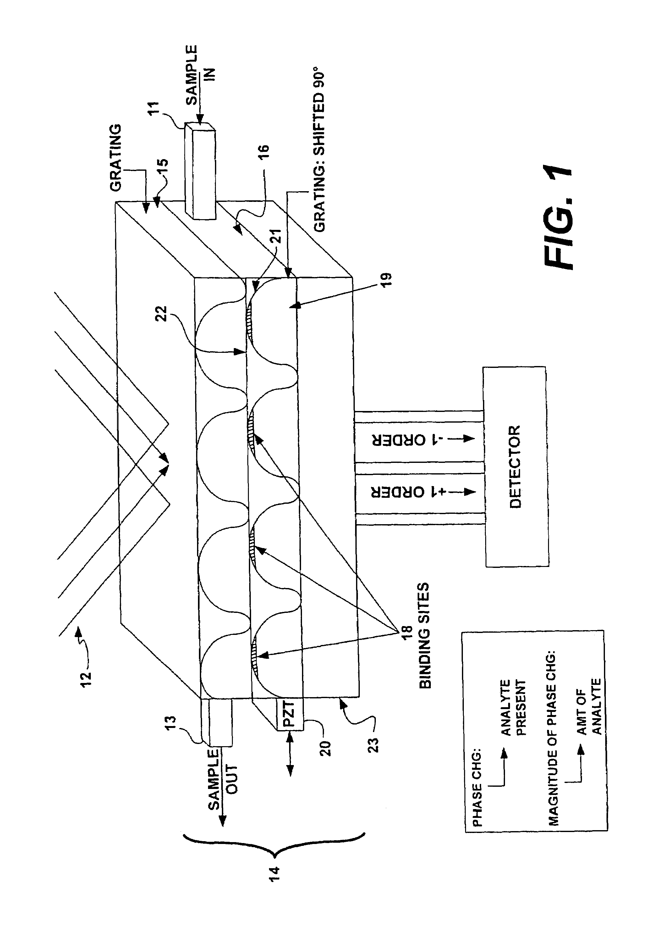
[0089]FIG. 6A shows an optical schematic of a system for detecting a single analyte. In the figure, the light source is a laser 50 emitting coherent light at a wavelength of 633 nm. This light is introduced into a beamsplitter 52 such that two point sources are created. A commercially available single mode fiber optic coupler can be used. These two point sources are then collimated by a lens 54 and directed towards the grating structure. The collimated beams are incident upon the grating structure 56 at an angle corresponding to the +1 and −1 diffraction orders generated by a 4 um period grating. This yields a ˜9 degrees angle of incidence. By using a lens with a 25 mm focal length a point source separation of 7.8 mm at the output of the fiber coupler can be realized. Two gratings, such as that depicted in FIG. 5 are used in the grating structure 56. The two gratings are translated by ¼ period with respect to each other and the separation between the two allows for fluid flow. A gra...

example 3

Multiple Analyte Detection—FIG. 7

[0090]Several detection configurations for multiple analyte detection are depicted in FIG. 7.

[0091]The layout shown in FIG. 7 can be adapted to accommodate multiple analyte detection by modifying the grating assembly to include multiple gratings, each designed to detect different analyte. The grating structure may be placed on a stage such that each grating may be translated to pass under the probing beam of the optical system, much like a ‘stepper’ in photolithography. FIG. 7A illustrates such a system. Such gratings range in size from 10 um and greater.


PUM


Abstract

A fast, accurate and reliable sensor applicable to chemical and biological analytes resides in an optical grating-based sensor, sensing system, and method of use. The sensor, configured for use with an illumination source and a signal detector in the system embodiment, includes first and second periodic diffraction gratings superimposed and shifted laterally relative to each other by a distance of less than one period, such that the illumination from the source is affected by both gratings before reaching the detector. An analyte recognition material disposed on a surface of the second diffraction grating. In operation, the output of the detector is first used to establish a baseline optical phase signal. The analyte recognition material is exposed to a sample, and the output of the detector is used to to determine a second optical phase signal. The baseline optical phase signal is compared to the second optical phase signal to detect the presence of the analyte, if any, in the sample. The analyte recognition material may be an antibody, nucleic acid, lectin or other substance. The sample may obtained from a mammal, including a human, plant, or the environment.

Description

FIELD OF THE INVENTION[0001]This invention relates to sensor devices for detecting chemical and biological agents. In particular, the invention relates to chemical and biological agent sensor devices that detect phase changes in light incident on two diffraction gratings.BACKGROUND OF THE INVENTION[0002]Biological weapons, infectious diseases, and environmental pathogens threaten both military and civilian personnel. Current technology lacks the capability to accurately detect the presence of trace amounts of chemical and biological warfare agents quickly and reliably.[0003]Current technologies include those involving detection of analytes labeled with a fluorescent, photo-luminescent, radioactive or enzymatic marker. This requirement includes additional steps and expense to the detection process, a significant disadvantage when prompt detection is necessary.[0004]Another broad category of currently used sensors includes those that employ optical waveguides. Waveguide sensors typica...

Claims


Application Information

Patent Timeline
IPC IPC(8): G01B9/02G01N21/00G01N21/03G01D5/353
CPCG01N21/4788G01D5/35303
Inventor ANGELEY, DAVID
Owner VERIDIAN SYST
Learn More