Surface acoustic wave sensor
a surface acoustic wave and sensor technology, applied in the direction of gravitational wave measurement, using reradiation, and analysing fluids using sonic/ultrasonic/infrasonic waves, etc., can solve the problems of insertion loss, decreasing sensitvity, and not being suitable for liquid environments, so as to improve the sensitivity of the sensor and the effect of increasing the sensitivity
- Summary
- Abstract
- Description
- Claims
- Application Information
AI Technical Summary
Benefits of technology
Problems solved by technology
Method used
Image
Examples
example 1
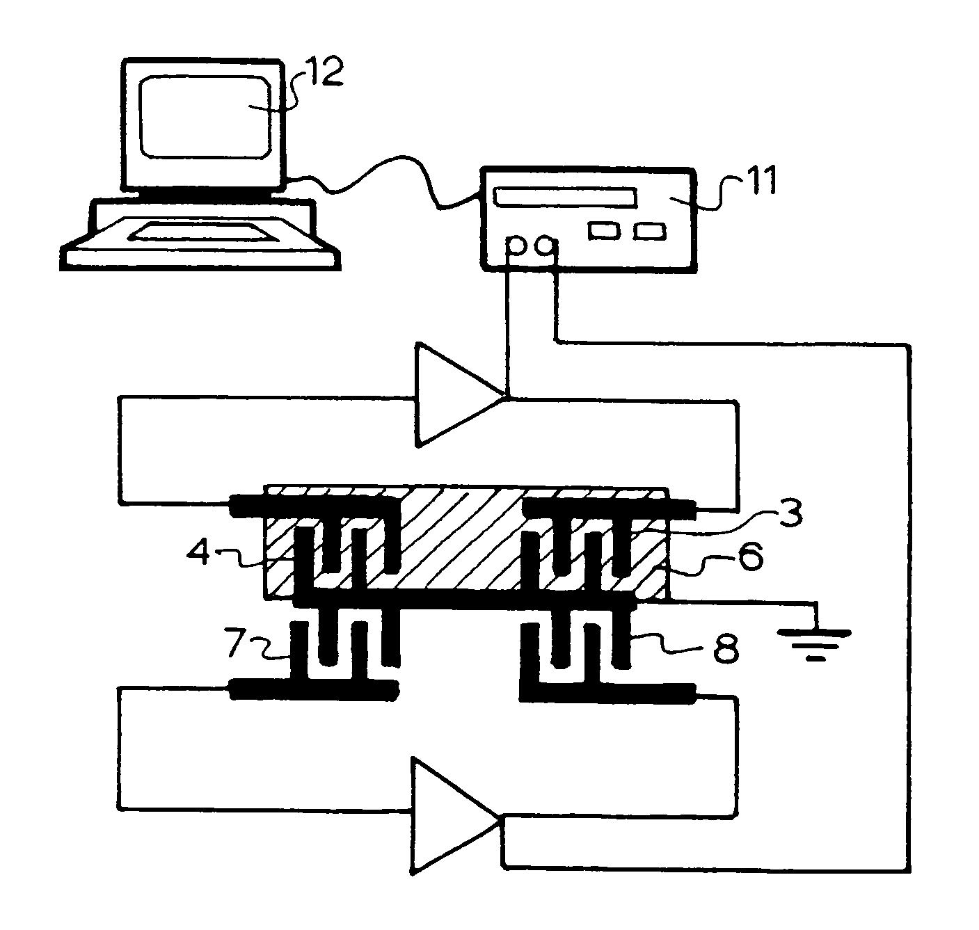
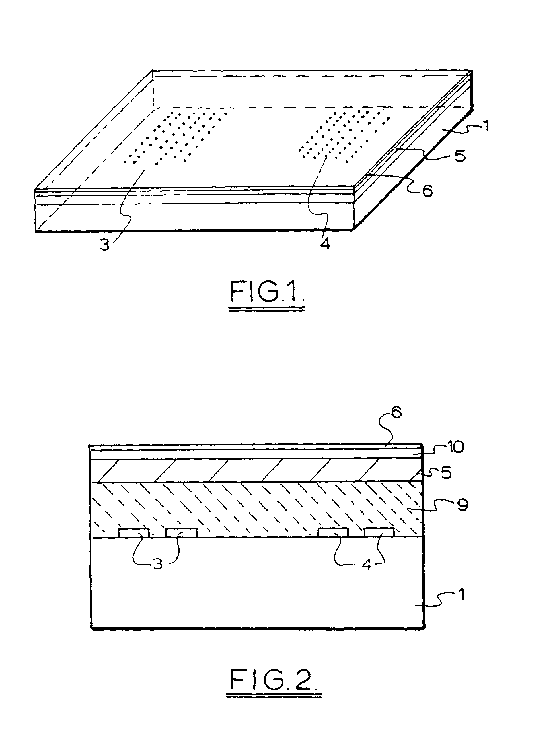
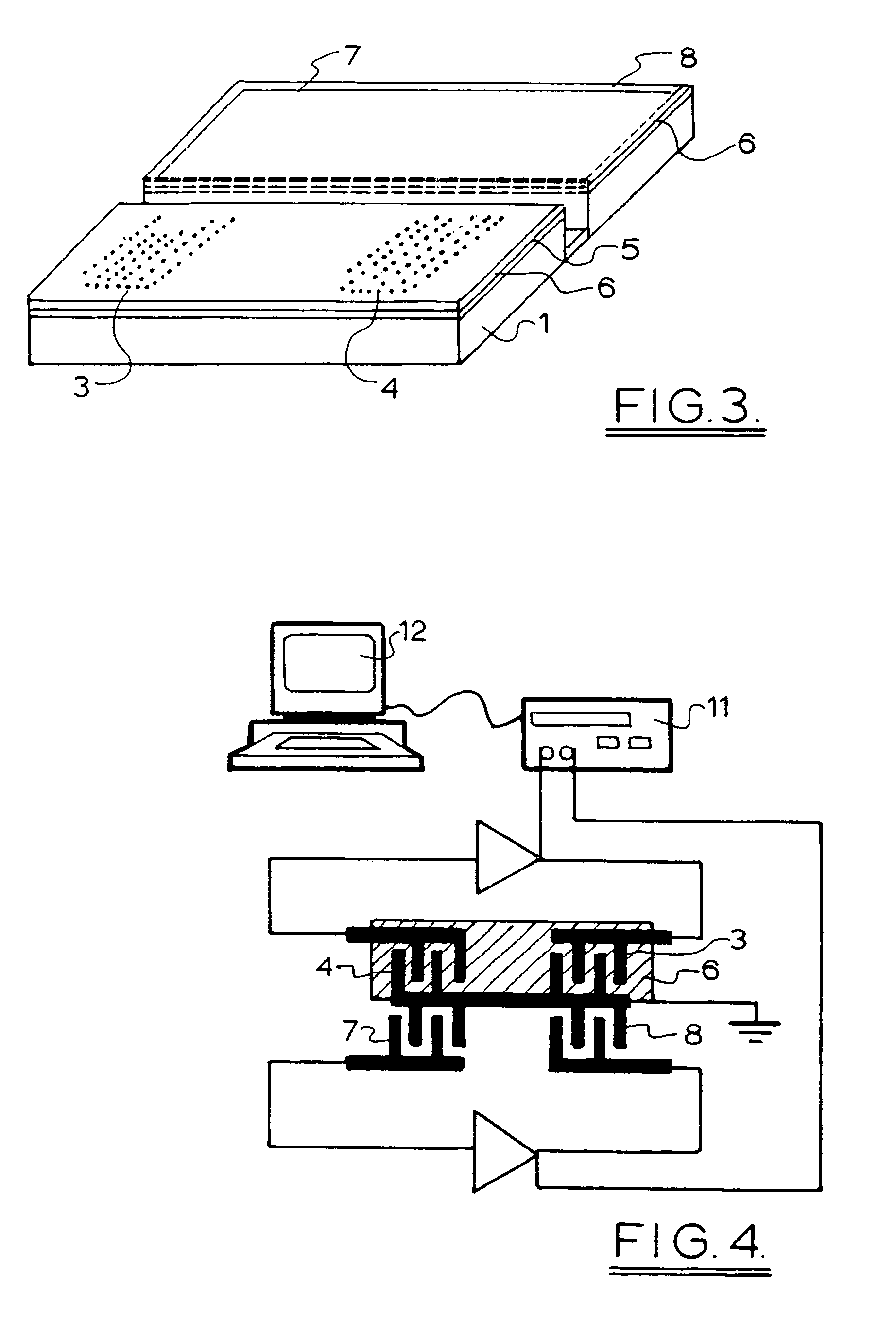
[0050]A dual line ZnO / 90° rotated ST-Cut Quartz crystal structure is fabricated with a ZnO layer ranging from 0 to 3.2 microns. A 15 nm Cr(5 nm) / Au(12 nm) layer is deposited as the sensitive layer over one of the delay lines. Cr / Au grows along the ZnO cylinders which increases the sensing surface of the gold.
[0051]Coupling coefficient, temperature coefficient velocity, insertion loss have been studied as a function of layer thickness. Magnitudes have been compared with SiO2 / 90° rotated ST-cut quartz crystal structure. The love wave transducers are fabricated on 0.5 mm thick 90° rotated ST-cut quartz crystal wafers. The transmit and receive IDT's consisted of 64 and 16 finger pairs in input and output ports respectively. The utilised acoustic wavelength is 50 microns. The acoustic centre to centre distance of transmitting and receiving IDT's is 60 wavelengths and aperture was chosen as 50 wavelengths.
[0052]ZnO films of different thicknesses were deposited by a r.f. magnetron sputtere...
example 2
[0058]An example of the response of the system to a sequence of different solutions is shown in FIG. 6.
[0059]The sensitive layer is gold. A flow of IgG (Immuno-Globulin G, 10 ng / ml) and BSA (Bovine Serum Albumin, 0.01 mg / ml) in 7.4 pH buffer pumped into the liquid cell with a flow rate of 0.05 ml / minute.
[0060]With the purge of IgG solution in buffer, IgG particles are adsorb to Au surface. It causes a frequency shift of about 4 KHz. Then the flow of buffer continues till all IgG dissociate from the surface. Afterwards, BSA is used to cover the Au surface and the surface of the reference transducer. By covering the sensitive layer there will be no adsorption and response occurs with another flow of IgG solution. Afterwards, Au surface was cleaned with a purge of Sodium Acetate solution. Then IgG solution liquid would be pumped and there will be the same frequency shift due to the adsorption of IgG particles on the Au surface. It shows the experiment is repeatable and only responds to...
example 3
[0068]For gas sensing experiments, the thickness of the ZnO layer was 2.8 μm giving an operational frequency of 90 MHz for the periodicity of 50 μm. The sensor was heated to 350° C. by a micro-heater located beneath the device.
[0069]The sensor was exposed to different concentrations of oxygen in nitrogen gas to investigate the response the Love mode SAW sensor. The response to 100 ppm of oxygen in nitrogen is shown in FIG. 7. Exposing the device to oxygen gas increases the operational frequency of the system. This increase in frequency is almost +18 kHz. For oxygen, the response and recovery times are continuous which stand for a single reaction on the surface.
[0070]The response of the sensor to different oxygen concentrations is shown in FIG. 8. The response of the sensor to 50 ppm is equal to −11 kHz. If the response from this point onward would continue to be linear, then the response of the device to 0.5 ppm will be equal to 110 Hz. The noise of the system is approximately 50 Hz...
PUM
| Property | Measurement | Unit |
|---|---|---|
| propagation speed | aaaaa | aaaaa |
| phase velocity | aaaaa | aaaaa |
| thick | aaaaa | aaaaa |
Abstract
Description
Claims
Application Information
 - R&D
- Intellectual Property
- Life Sciences
- Materials
- Tech Scout
- Unparalleled Data Quality
- Higher Quality Content
- 60% Fewer Hallucinations
Browse by: Latest US Patents, China's latest patents, Technical Efficacy Thesaurus, Application Domain, Technology Topic, Popular Technical Reports.
© 2025 PatSnap. All rights reserved.Legal|Privacy policy|Modern Slavery Act Transparency Statement|Sitemap|About US| Contact US: help@patsnap.com


