Neutron detector employing doped pyrolytic boron nitride and method of making thereof

a boron nitride and neutron detector technology, applied in the field of neutron detectors, can solve the problems of inefficient use of scintillation detectors for detecting neutrons, difficult detection of neutron particles, limited utility, etc., and achieve the effect of raising the energy level

Inactive Publication Date: 2006-04-25
GENERAL ELECTRIC CO
View PDF13 Cites 10 Cited by
  • Summary
  • Abstract
  • Description
  • Claims
  • Application Information

AI Technical Summary

Problems solved by technology

Accordingly, the presence of neutron particles is difficult to detect.
The Geiger counter is a gas filled tube which may be filled with 3He or with BF3, but has limited utility since it is both bulky and expensive to manufacture.
Because optics cannot gather all of the light and some of the light is reabsorbed by the scintillating material, thus the use of scintillation detectors for detecting neutrons is inefficient.
Furthermore, light detectors have an inherent sensitivity limit to all wavelengths.
Attempts have been made in the semiconductor detector prior art to capture neutrons using a pBN detector fabricated in a conventional fashion, and oriented to collect neutrons through the deposition layers, i.e., the predominantly c-axis direction, but have yielded poor results.

Method used


Image

  • Neutron detector employing doped pyrolytic boron nitride and method of making thereof
  • Neutron detector employing doped pyrolytic boron nitride and method of making thereof
  • Neutron detector employing doped pyrolytic boron nitride and method of making thereof

Examples


example 1

[0048]In this first example, pyrolytic boron nitride layers are deposited on a graphite mandrel by passing BCl3, NH3 in a graphite vacuum furnace based CVD reactor. Reactant gases are introduced into a heated chamber (heated to a temperature in the range of 1600°–1900° C.) within a water-cooled steel vacuum chamber. The graphite mandrel is placed above a nozzle through which reactant gases flow into the heated chamber. Water-cooled coaxial injectors are used. Temperature is monitored by an optical pyrometer. Pressure is monitored by a vacuum transducer.

[0049]In the deposition process, CH4 is introduced along with BCl3 at feed rates adjusted for the carbon concentration in the pBN to be kept at about 3 wt. % or less (by adjusting the C / B ratio and O / C ratio in the feed gases, specifically the rates of CH4 relative to BCl3).

[0050]The electrical resistivity of the doped pBN composite is measured at about 2.1×10⁸ ohm-cm.

example 2

[0051]In example 2, an additional feed stream of an oxygen precursor is introduced to adjust the oxygen concentration in the pBN. The BCl3 feed stream is maintained at about 0.5 slpm. The NH3 is maintained at about 1.5 slpm. The furnace temperature is about 1800° C. Vacuum pressure is maintained at about 0.5 mm Hg. At intervals of about every 15 minutes, a pulse of CO feed rate of about 0.5 slpm is introduced for about 5 seconds to sufficiently incorporate oxygen uniformly along the surface of the pBN material.

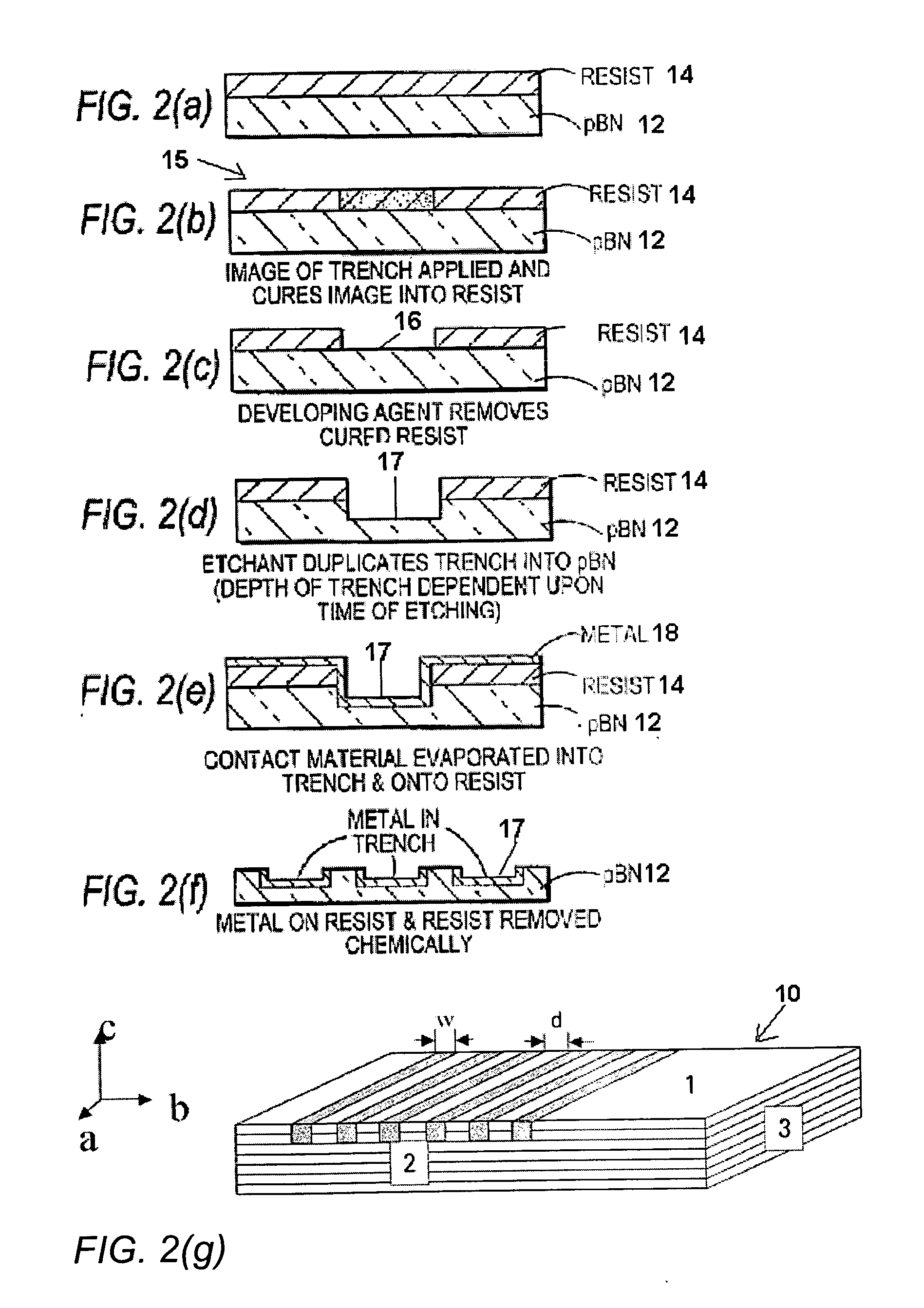
[0052]The deposition rate is at about 100–180 microns per hour. After the deposition, pBN layers may be obtained by peeling them off the pBN deposit. The ped strength between the pBN layers is measured using a double cantilever beam (DCB) test known in the art to measure peel strength between the surface layer interfaces. The peel strength is found to be about 1.5 N / mm or less.

example 3

[0053]Example 2 is repeated for to produce layers of doped pBN with engineered weaker interfaces at intervals of about every 100 microns. The layers are peeled of by attaching an adhesive tape (3M's Scotch Tape) and pulling the tape in a direction normal to the deposited layer, thus separating the layers.

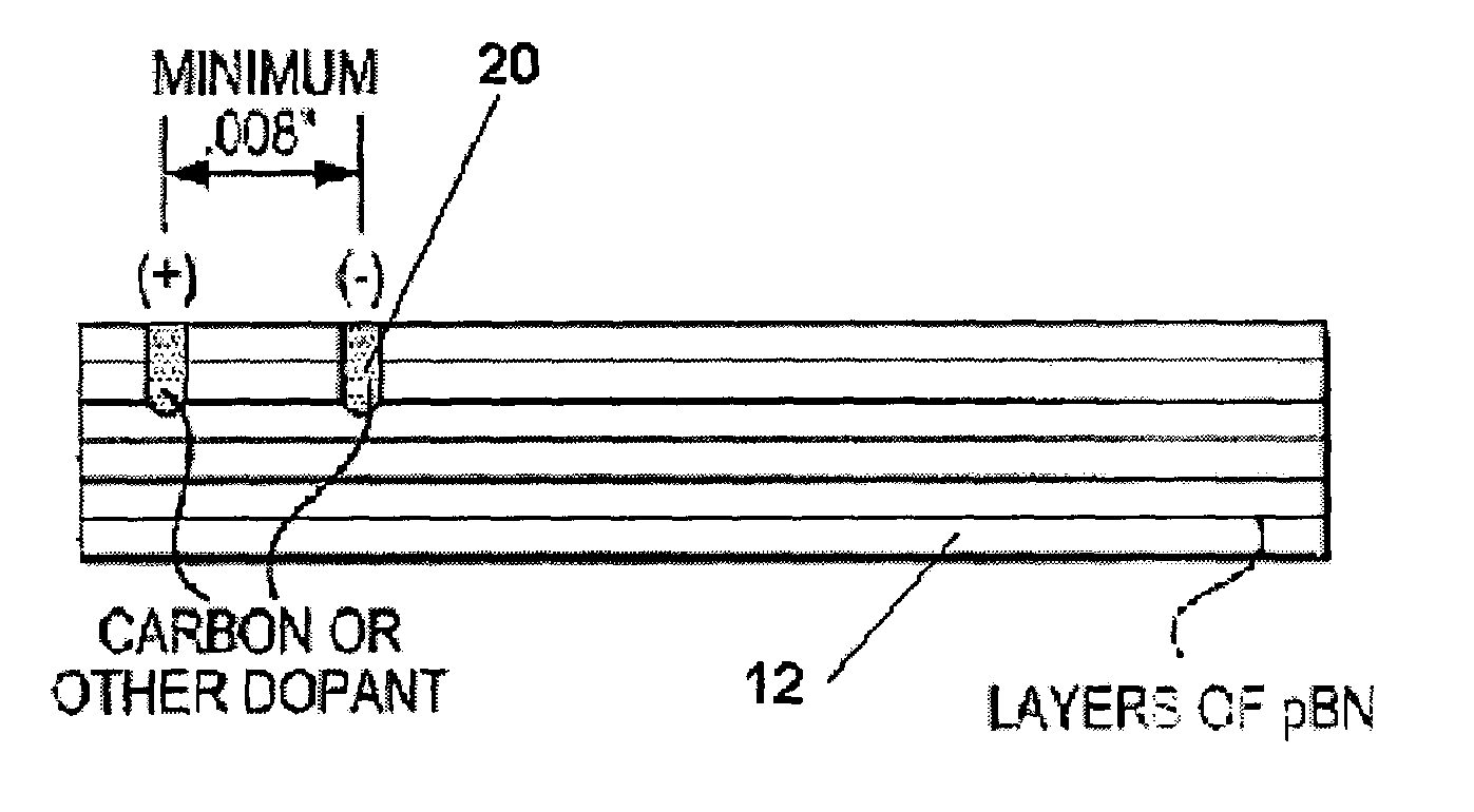
[0054]In the next step, electrodes (silver filled epoxy) are applied to the planar surfaces of each layer. Once the electrodes are attached on either side, a high voltage gradient is generated by applying suitable level of D.C. field. The detector is then attached to a schematic incorporating electronic circuit as shown in FIG. 5 for detection of pulses generated by neutron-boron interaction.


PUM


Abstract

A system for measuring a thermal neutron emission from a neutron source is provided. The system employs a detector utilizing a plurality of doped pBN layers, wherein the doped pBN layers are doped with at least one dopant across an a-b plane of the layers for an electrical resistivity of 1014 ohm-cm or less.

Description

CROSS-REFERENCE TO RELATED APPLICATIONS NONEFIELD OF THE INVENTION[0001]This invention relates to a neutron detector, and more particularly to a solid state semiconductor neutron detector formed from pyrolytic boron nitride, and to a method of manufacture of a pyrolytic boron nitride neutron detector.BACKGROUND OF THE INVENTION[0002]Neutrons are uncharged elemental particles which do not ionize matter as they pass through it. Accordingly, the presence of neutron particles is difficult to detect. Thermal neutrons are produced by splitting atoms such as Uranium 235 in a nuclear reactor and slowing the velocity of the fissioned neutrons through collisions with some moderating material. Neutron detection in the prior art is typically performed with either gas detectors or scintillators. A Geiger counter is a conventional gas detector for detecting neutrons. The Geiger counter is a gas filled tube which may be filled with 3He or with BF3, but has limited utility since it is both bulky an...

Claims


Application Information

Patent Timeline
Patent Type & Authority Patents(United States)
IPC IPC(8): G01T3/00G01T3/08
CPCG01T3/08
Inventor SANE, AJIT YESHWANTLEIST, JON RUSSSELLMOORE, ARTHUR WILLIAM
Owner GENERAL ELECTRIC CO
Why Eureka
Try Eureka