Automatic tuning of motion controllers using search techniques

a technology of motion controller and search technique, applied in the direction of electric controllers, program control, instruments, etc., can solve the problems of not providing any guarantees about the achievement of position trajectory, all of these methods have substantial drawbacks, and none of these techniques effectively account for many real-world nonlinear effects

Active Publication Date: 2006-04-25
NATIONAL INSTRUMENTS
View PDF15 Cites 18 Cited by
  • Summary
  • Abstract
  • Description
  • Claims
  • Application Information

AI Technical Summary

Benefits of technology

[0061]It should be noted that there is a difference between the stopping conditions and the halting conditions. Notice that in the above embodiment, the method performs two types of search. The first is a ‘local search’ process that occurs at a constant temperature (i.e., transition probability to a point that does not improve performance), and is designed to test various points in the space for the desired optimum. This is completed when the ‘stopping condition’ is reached. The second search process relates to the “annealing” phenomenon, where the probability of a transition to a point of lower performance slowly decreases, with decreasing ‘temperature’. This aspect of the process completes when the “halting condition” is reached. Note that this type of search process is particularly useful when there is no analytical model for the process, and so no gradient may be computed for standard gradient descent (or ascent) approaches. Thus, by testing a large number of points and taking the ‘best transition’, the process of gradient descent is effectively simulated. However, local minima, the famous pitfall in gradient descent methods, must be avoided. This may be achieved by providing a finite small probability of an ‘uphill’ transition. Now the global step based on a decreasing temperature value is actually reducing the strength or likelihood of this ‘uphill’ transition by successively lowering the maximum allowable uphill jump, thus encouraging convergence to a specific optimum.
[0064]Thus, in various embodiments of the system and method described above, a single or multiple axis motion control system may be automatically tuned using experimental search techniques, e.g., simulated annealing. The search techniques may be based on a metric, e.g., a Euclidean norm, which quantifies the difference between a desired trajectory and a response trajectory of the system. This provides for great flexibility in applying motion control to a variety of different systems as compared to prior art autotuning systems and methods.

Problems solved by technology

Often, in the presence of static friction and sensor noise, the system may quickly enter the settling band but hunt for the ‘correct’ position within a 1–2 count interval.
However, this gain set only yields stability of a single axis, and does not provide any guarantees about the achievement of the position trajectory.
All of these methods have substantial drawbacks.
Additionally, none of these techniques effectively account for many real world nonlinear effects, such as static friction, backlash, etc.
While research literature in the field discloses various techniques to address these effects using model-based approaches, some of the advanced techniques require substantial on-board instrumentation and data acquisition capabilities, which can be problematic for embedded systems in that there may not be enough on-board capacity (for storage and / or computation) to implement the algorithms.
However, there are many situations where they fail.
However, many motion control systems are high performance applications where these effects do become a problem and the traditional tuning techniques do not suffice.
Systems with time lag and high inertias: In systems that have significant amounts of time lag, the simple third order model does not capture this effect.
Often, problems manifest themselves along with new classes of systems, such as piezoelectric motors or special purpose electrical drives which are used in the motion control system.
Lastly, but possibly most importantly, the above technique ignores many aspects of how a motion control loop is actually implemented.
Tuning the control loop for a step response does not guarantee achievement of the position profile.
However, the heuristics may rely on a number of assumptions that may not be valid for the system, e.g., assumptions related to mass, response times, etc.
Additionally, this type of iterated correction may not be feasible depending upon the application and device constraints, e.g., time constraints, memory, processor capabilities, etc.
For example, many motion control devices, such as embedded devices, do not permit an analysis intensive program to be run on board.
This leads to the possibility of mistakes when the real process or system is not properly described by the assumed model.

Method used


Image

  • Automatic tuning of motion controllers using search techniques
  • Automatic tuning of motion controllers using search techniques
  • Automatic tuning of motion controllers using search techniques

Examples


first embodiment

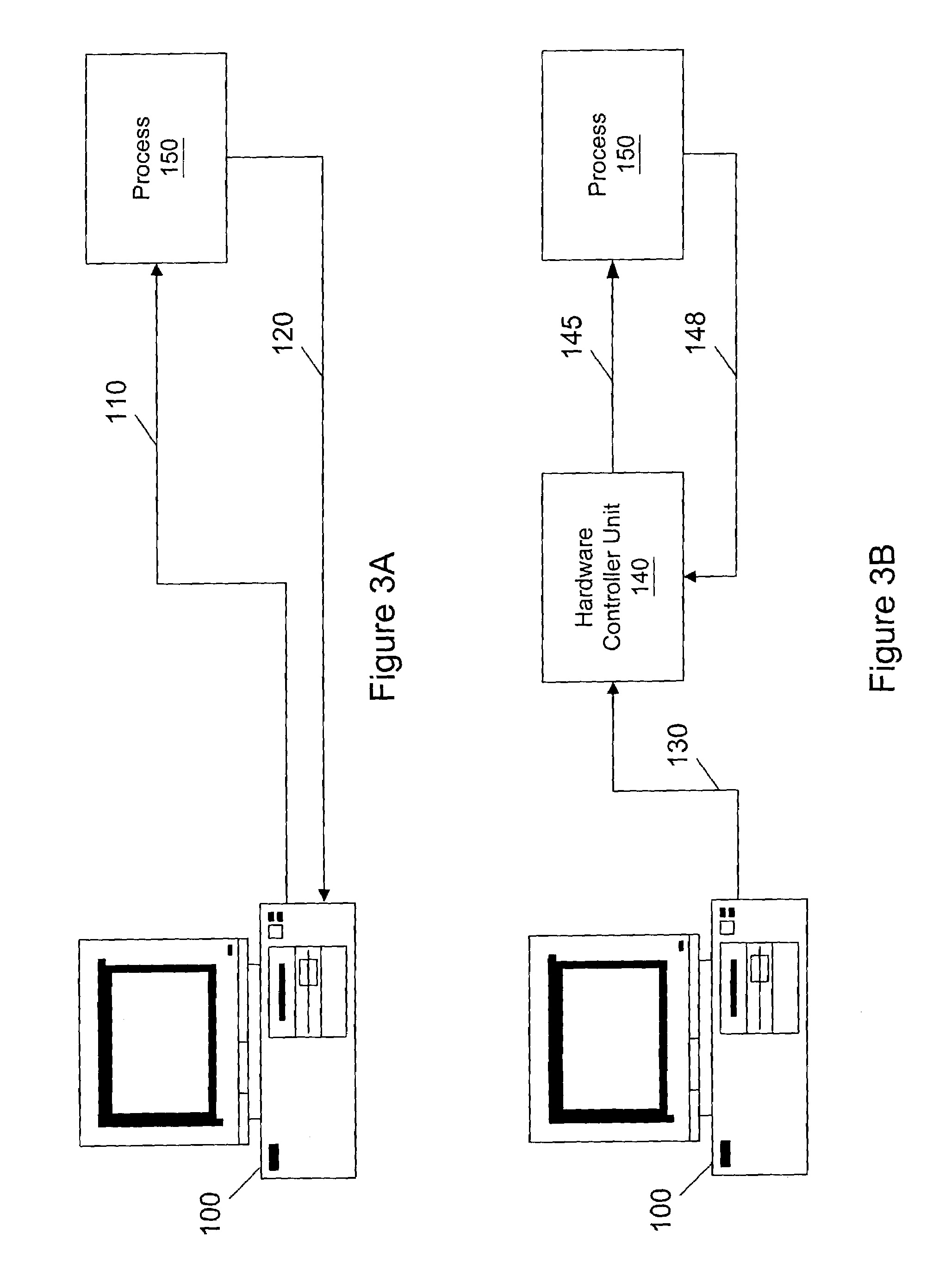
[0082]FIG. 3A illustrates the system of the present invention that includes a computer 100, and process 150. Computer 100 supplies actuating signals to the process 150 through actuating bus 110. It is noted that a D / A conversion device (not shown) is preferably included in this embodiment to convert the actuating signals from a digital form to an analog form. Furthermore, computer 100 senses the process variable PV through measurement bus 120. Data acquisition logic (not shown) such as an A / D conversion device is preferably employed to convert the process variable from analog to digital form. Thus, computer 100 operates on a stream of samples of the process variable (PV).

[0083]In one embodiment, the controller may be implemented in software, i.e., a controller program, which may be stored in a memory of the computer 100, and executed by a processor comprised on the computer 100. An autotuning algorithm may also be implemented in software, i.e., in an autotuning program, stored and e...

second embodiment

[0085]FIG. 3B illustrates the system of the present invention which includes computer 100, process 150, and external hardware controller unit 140, e.g. controller. Thus hardware controller unit 140 may implement the controller, either in software or in programmable logic. Computer 100 is coupled to hardware controller unit 140 through a signal bus 130. Hardware controller unit 140 drives process 150 with actuating signal u through process bus 145. Also, hardware controller unit 140 senses process variable PV through sensing bus 148. Hardware controller 140 preferably includes an A / D conversion device to convert the process variable received via sensing bus 148 from analog to digital form.

[0086]In this second embodiment of the present invention, the computer 100 sends a setpoint signal SP, which is the target equilibrium value of the process variable PV to the hardware controller unit 140 through signal bus 130. The hardware controller unit 140 performs at least a portion of the auto...


PUM


Abstract

System and method for user configuration of an autotuning algorithm for a controller in a motion control system. A desired trajectory in one or more dimensions for the motion control system is received. Values of one or more gains for a controller are initialized. A response trajectory of the controller and motion control system in response to the desired trajectory is received, and an error determined between the response trajectory and the desired trajectory. A gain space is then experimentally searched to determine final values of the one or more gains for the controller that minimize the error (e.g., Euclidean norm) between the response trajectory and the desired trajectory, e.g., via simulated annealing, or other stochastic, quasi-random, and / or deterministic approaches. After experimentally searching, the controller is operable to control the motion control system substantially in accordance with the desired trajectory using the determined values of the one or more gains.

Description

FIELD OF THE INVENTION[0001]The present invention relates to the automatic tuning of motion controllers, and in particular to a system and method for automatic tuning of single or multiple axis motion controllers with using search techniques.DESCRIPTION OF THE RELATED ART[0002]The phrase “motion control” refers to controlled displacement of an actuator along trajectories in one or more dimensions. The motions in individual dimensions are generally controlled as independent “axes” with separate control loops that are synchronized at a higher level. Alternatively, in some approaches a multiple input-multiple output (MIMO) control structure is used to control all motion in all the dimensions at once.[0003]Despite the development of more advanced control strategies, the majority of industrial control systems still use PID (Proportional-Integral-Derivative) controllers because they are standard industrial components, and their principles are well understood by engineers. Moreover, due to...

Claims


Application Information

Patent Timeline
Patent Type & Authority Patents(United States)
IPC IPC(8): G05B11/01G05B13/04G05B19/414
CPCG05B13/042G05B19/414G05B2219/42152G05B2219/34208
Inventor RAMAMOORTHY, SUBRAMANIANFALCON, JEANNE S.
Owner NATIONAL INSTRUMENTS
Why Eureka
Try Eureka