Method and apparatus for micro-jet enabled, low energy ion generation and transport in plasma processing

a plasma processing and low energy ion technology, applied in the direction of plasma technique, electrical apparatus, electric discharge tube, etc., to achieve the effect of reducing the strength of the electric field, enhancing the ion content of the plasma exhaust, and reducing the strength of the sheath potential exerted on the ions contained in the secondary plasma discharg

Inactive Publication Date: 2006-05-02
LAM RES CORP
View PDF22 Cites 89 Cited by
  • Summary
  • Abstract
  • Description
  • Claims
  • Application Information

AI Technical Summary

Benefits of technology

[0008]The previously discussed drawbacks and deficiencies of the prior art are overcome or alleviated by a method for creating and transporting low-energy ions for use in plasma processing of a semiconductor wafer. In an exemplary embodiment of the invention, the method includes generating plasma from a gas species to produce a plasma exhaust. The plasma exhaust is then introduced into a processing chamber containing the wafer. The ion content of the plasma exhaust is enhanced by activating a supplemental ion source as the plasma is introduced into the processing chamber, thereby creating a primary plasma discharge therein. Then, the primary plasma discharge is directed into a baffle plate assembly, where a secondary plasma discharge is created as the plasma exits the baffle plate assembly. The strength of the sheath potential exerted on ions contained in the secondary plasma discharge is reduced, the sheath potential resulting from the primary plasma discharge.

Problems solved by technology

The resulting reduced strength of the electric field accelerates the ions through a lower potential, thereby causing

Method used


Image

  • Method and apparatus for micro-jet enabled, low energy ion generation and transport in plasma processing
  • Method and apparatus for micro-jet enabled, low energy ion generation and transport in plasma processing
  • Method and apparatus for micro-jet enabled, low energy ion generation and transport in plasma processing

Examples


Embodiment Construction

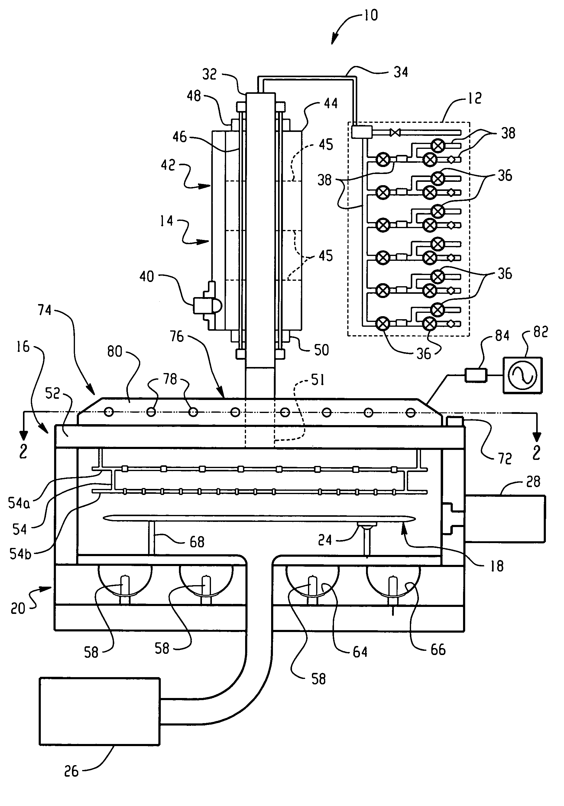
[0021]A novel low-energy ion generation and transport mechanism is disclosed herein; this mechanism enhances the chemical decomposition and subsequent volatilization of a carbonized top layer of an ion-implanted photoresist in a uniform manner, without also exposing the wafer to the potentially harmful effects of high-energy ion bombardment due to high sheath voltages. Such a “soft” ion assisted technique takes advantage of the synergy between the ions generated by a supplemental ion source in the ash tool and the chemical reactants already present, thereby producing a faster reaction than can be achieved by either, or the simple sum of these components.

[0022]It is believed that the ions contribute both “physical” kinetic energy, as well as “chemical” internal energy released upon reaction, thereby effectively lowering the activation energy for surface reactions. By shielding the wafer from the high sheath potentials characteristic of a conventional capacitive discharge, the ions ar...


PUM

PropertyMeasurementUnit
Densityaaaaaaaaaa
Electrical conductoraaaaaaaaaa
Strengthaaaaaaaaaa

Abstract

A method for creating and transporting low-energy ions for use in plasma processing of a semiconductor wafer is disclosed. In an exemplary embodiment of the invention, the method includes generating plasma from a gas species to produce a plasma exhaust. The plasma exhaust is then introduced into a processing chamber containing the wafer. The ion content of the plasma exhaust is enhanced by activating a supplemental ion source as the plasma is introduced into the processing chamber, thereby creating a primary plasma discharge therein. Then, the primary plasma discharge is directed into a baffle plate assembly, thereby creating a secondary plasma discharge exiting the baffle plate assembly. The strength of an electric field exerted on ions contained in the secondary plasma discharge is reduced. In so doing, the reduced strength of the electric field causes the ions to bombard the wafer at an energy insufficient to cause damage to semiconductor devices formed on the wafer.

Description

CROSS-REFERENCE TO RELATED APPLICATIONS[0001]The present application is a divisional application of application Ser. No. 09 / 905,043, filed Jul. 31, 2001, now U.S. Pat. No. 6,761,796, which is a continuation in part of application Ser. No. 09 / 828,055, filed on Apr. 6, 2001, now abandoned, the disclosures of which are incorporated by reference herein in their entirety.BACKGROUND[0002]The present invention relates generally to the plasma processing of semiconductor wafers and, more specifically, to a low-energy ion generation and transport mechanism for use in plasma ashing systems.[0003]In the manufacture of integrated circuits, photolithography techniques are used to form integrated circuit patterns on a substrate. Typically, a semiconductor substrate is coated with a photoresist material, portions of which are exposed to ultraviolet (UV) radiation through a mask to image a desired circuit pattern on the photoresist. The portions of the photoresist left unexposed to the UV radiation ...

Claims


Application Information

Patent Timeline
IPC IPC(8): H01L21/302H01L21/461H05H1/46H01J37/32H01L21/3065
CPCH01J37/32192H01J37/321H01L21/3065
Inventor SRIVASTAVA, ASEEM KUMARSAWIN, HERBERT HAROLDSAKTHIEVEL, PALANIKUMARAN
Owner LAM RES CORP
Why Eureka
Try Eureka