Vitrified bond tool and method of manufacturing the same
- Summary
- Abstract
- Description
- Claims
- Application Information
AI Technical Summary
Benefits of technology
Problems solved by technology
Method used
Image

Examples
example 1
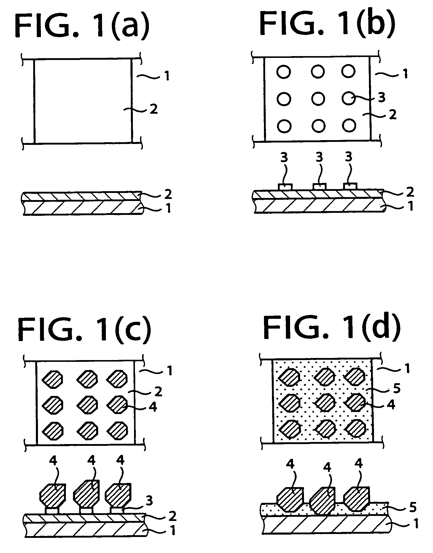
[0111]Initially, the generally disk-shaped support body 1 was prepared. The disk-shaped support body 1 was made of silicon nitride, and had a diameter of 100 mm and a thickness of 5 mm. The disk-shaped support body 1 had, in its outer peripheral portion, a protruding portion which was divided by eight slits into eight protrusions. These eight protrusions were arranged in the circumferential direction of the support body 1 at an angular pitch of 45°, and each of them had a width of 4 mm and a height of 1 mm. Each of the eight slits, which divided the protruding portion into the eight protrusions, had a width of 5 mm and a depth of 1 mm.
[0112]A paste including a borosilicate glass was printed on the entirety of a surface of each of the eight protrusions of the support body 1. The printing operation was repeated six times, so that a backing layer 2 having a predetermined thickness, for example, of 150 μm is formed on the entirety of the surface of the protrusion of the support body 1, ...
example 2
[0126]Initially, a generally disk-shaped support body 11 was prepared. The disk-shaped support body 11 was made of the same material as the support body 1 of Example 1, and was identical in shape to the support body 1 of Example 1. A paste including a borosilicate glass was pattern-printed on each protrusion of the support body 11 by using suitable masking means, so as to form a pattern layer 12 consisting of a plurality of dots each of which had a diameter of 100 μm, as shown in FIG. 3(a). The dots were positioned relative to each other so as to be arranged in a lattice, at a pitch of 300 μm between the adjacent ones of the dots.
[0127]Diamond abrasive grains 13 of #100 / #120 were sprinkled on each protrusion of the support body 11, by using a sieve of about #100, such that each one of the diamond abrasive grains 13 was held on the corresponding one of the dots of the pattern layer 12, as shown in FIG. 3(b). The support body 11 thus holding the diamond abrasive grains 13 was dried fo...
example 3
[0130]Initially, a generally disk-shaped support body 21 was prepared. The disk-shaped support body 21 was made of the same material as the support body 1 of Example 1, and was identical in shape to the support body 1 of Example 1. A paste including a borosilicate glass was pattern-printed on each protrusion of the support body 21 by using suitable masking means, so as to form a pattern layer 22 consisting of a plurality of dots each of which had a diameter of 100 μm, as shown in FIG. 4(a). The dots were positioned relative to each other so as to be arranged in a lattice, at a pitch of 300 μm between the adjacent ones of the dots.
[0131]Diamond abrasive grains 23 of #100 / #120 were sprinkled on each protrusion of the support body 21, by using a sieve of about #100, such that each one of the diamond abrasive grains 23 was held on the corresponding one of the dots of the pattern layer 22, as shown in FIG. 4(b). The support body 21 thus holding the diamond abrasive grains 23 was dried fo...
PUM
| Property | Measurement | Unit |
|---|---|---|
| Distance | aaaaa | aaaaa |
Abstract
Description
Claims
Application Information
 - Generate Ideas
- Intellectual Property
- Life Sciences
- Materials
- Tech Scout
- Unparalleled Data Quality
- Higher Quality Content
- 60% Fewer Hallucinations
Browse by: Latest US Patents, China's latest patents, Technical Efficacy Thesaurus, Application Domain, Technology Topic, Popular Technical Reports.
© 2025 PatSnap. All rights reserved.Legal|Privacy policy|Modern Slavery Act Transparency Statement|Sitemap|About US| Contact US: help@patsnap.com