Substituted diphenylanthracene compounds for organic electroluminescence devices

a technology of diphenylanthracene and organic electroluminescence, which is applied in the direction of discharge tube luminescnet screen, other domestic articles, organic semiconductor devices, etc., can solve the problems of insufficient light emission efficiency, heat resistance and life, and the inability to use organic el devices for practical applications, etc., to achieve excellent light emission and heat resistance efficiency, excellent color purity

Inactive Publication Date: 2006-05-30
IDEMITSU KOSAN CO LTD
View PDF12 Cites 102 Cited by
  • Summary
  • Abstract
  • Description
  • Claims
  • Application Information

AI Technical Summary

Benefits of technology

[0006]The present invention has been made to overcome the above problems and has an object of providing a novel compound which exhibits excellent efficiency of light emission and heat resistance, has a long life and emits bluish light having excellent purity of color and an organic electroluminescence device utilizing the novel compound.

Problems solved by technology

Organic EL devices used heretofore have higher driving voltages, lower luminances of emitted light and lower efficiencies of light emission than inorganic light emitting diodes and, moreover, the properties of organic EL devices deteriorate rather rapidly.
Therefore, organic EL devices have not been used for practical applications.
Although the properties of recent organic EL devices have been improved remarkably, the efficiency of light emission, the heat resistance and the life are not sufficient for practical applications.
However, since the above compound used in the device contains two or three anthracene structures bonded through a conjugated group, the organic EL device has a small energy gap and exhibits poor purity of color in emission of blue light.
Moreover, since this compound is easily oxidized, impurities tend to be contained and a problem arises with respect to purification.
However, the prepared organic EL devices exhibit low efficiencies of light emission and cannot be used for practical applications.
However, this device exhibits an efficiency of light emission as low as 1 cd / a and cannot be used for practical applications.
However, this device exhibits an efficiency of light emission as low as 2 cd / A and cannot be used for practical applications although the device exhibits excellent heat resistance due to the substitution with an aryl group at the m-position.

Method used

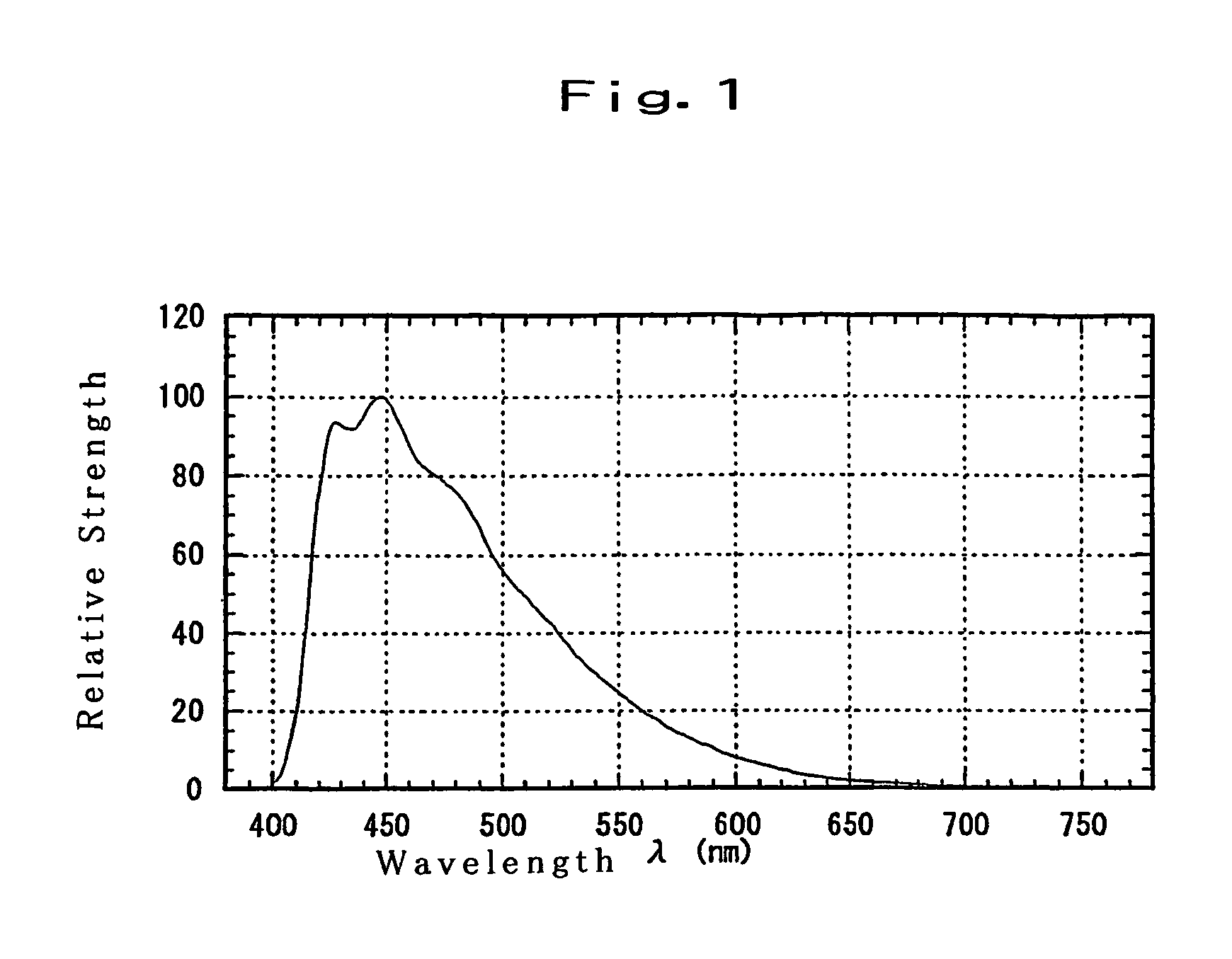

Image

  • Substituted diphenylanthracene compounds for organic electroluminescence devices
  • Substituted diphenylanthracene compounds for organic electroluminescence devices
  • Substituted diphenylanthracene compounds for organic electroluminescence devices

Examples


synthesis example 1

Compound 14

(1) Synthesis of 2,2′-dibromobiphenyl

[0076]Under an atmosphere of argon, 1,2-bromobenzene (25 g, 0.11 mole) was dissolved into anhydrous THF (240 ml) and the resultant solution was cooled at −67° C. in a dry ice / methanol bath. To the cooled solution, a hexane solution of n-butyllithium (1.50 mole / liter, 35 ml, 53 mmole, 0.5 eq) was slowly added dropwise over 5 minutes. The resultant mixture was stirred at −67° C. for 1 hour and then at the room temperature for 3 hours. To the obtained reaction mixture, a saturated aqueous solution of ammonium chloride (100 ml) was added. The formed organic layer was separated, washed with a saturated aqueous solution of sodium chloride (50 ml) and dried over anhydrous magnesium sulfate. Then, the solvent was removed by distillation and a brown liquid (about 19 g) was obtained. The obtained liquid was purified by the column chromatography (silica gel / hexane) and white needle crystals (9.5 g, 57%) were obtained.

[0077]1H-NMR (CDCl3, TMS) δ: ...

synthesis example 2

Compound 15

(1) Synthesis of 1-(2-bromophenyl)naphthalene

[0084]Under an atmosphere of argon, 2-bromoiodobenzene (7.0 g, 25 mmole), naphthaleneboronic acid (4.0 g, 23 mmole) and tetrakis(triphenylphosphine)palladium(0) (0.5 g, 0.43 mmole, 1.7% Pd) were dissolved into toluene (50 ml). To the obtained solution, an aqueous solution of sodium carbonate (7.3 g, 69 mmole, 3 eq / 35 ml) was added. The resultant solution was heated under refluxing for 10 hours and left standing for one night. The formed organic layer was separated, washed with a saturated aqueous solution of sodium chloride (50 ml) and dried with anhydrous magnesium sulfate. Then, the solvent was removed by distillation and a yellow oil was obtained. The obtained oil was purified by the column chromatography (silica gel / hexane, hexane+3% dichloromethane and hexane+10% dichloromethane, successively) and white needle crystals (5.4 g, 83%) were obtained.

[0085]1H-NMR (CDCl3, TMS) δ: 7.3 to 7.8 (9H, m), 7.90 (2H, dd, J=8 Hz, 2 Hz)

(2...

synthesis example 3

Compound 17

(1) Synthesis of 9-phenanthreneboronic acid

[0090]Under an atmosphere of argon, 9-bromophenanthrene (15 g, 58 mmole) was dissolved into anhydrous ether (150 ml) and the resultant solution was cooled at −35° C. in a dry ice / methanol bath. To the cooled solution, a hexane solution of n-butyllithium (1.50 mole / liter, 43 ml, 65 mmole) was added dropwise and the resultant mixture was stirred at −20° C. for 1 hour. After the reaction mixture was cooled at −67° C., a solution (30 ml) of triisopropoxyborane (37 ml, 0.16 mole, 2.8 eq) in anhydrous ether was added the resultant mixture was stirred at −65° C. for 1 hour and at the room temperature for 2 hours and left standing for one night. To the obtained reaction mixture, a 10% hydrochloric acid (150 ml) was added. After the resultant mixture was stirred at the room temperature for 1 hour, the formed organic layer was separated, washed with a saturated aqueous solution of sodium chloride (50 ml) and dried with anhydrous magnesium ...


PUM

PropertyMeasurementUnit
peak wavelengthaaaaaaaaaa
work functionaaaaaaaaaa
transmittanceaaaaaaaaaa

Abstract

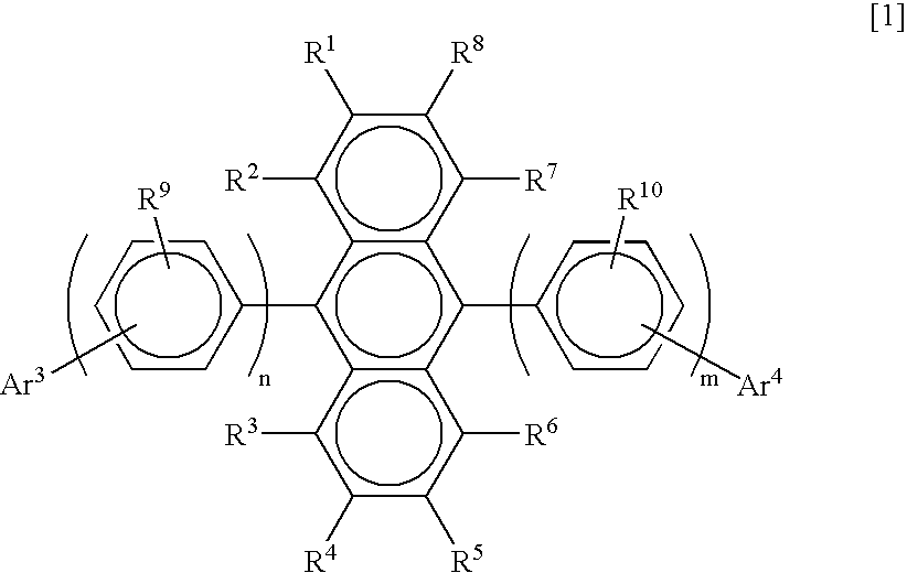
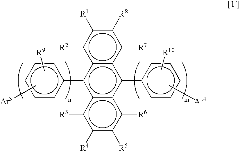
A compound having a of the present invention has the diphenylanthracene structure at the center and a specific structure substituted with an aryl group at end portions. An organic electroluminescence device comprises a plurality of layers of thin films of organic compounds which comprise a light emitting layer or a plurality of layers comprising a light emitting layer and are disposed between a pair of electrodes and at least one of the layers of thin films of organic compounds comprises the above compound. The compound exhibits excellent efficiency of light emission and heat resistance, has a long life and emits bluish light having excellent purity of color and the organic electroluminescence device comprises the compound and exhibits the same advantageous properties.

Description

TECHNICAL FIELD[0001]The present invention relates to a novel compound which is used as a light source such as a planar light emitting member of wall televisions and a back light of displays, exhibits excellent efficiency of light emission and heat resistance, has a long life and emits bluish light having excellent purity of color and to an organic electroluminescence device utilizing the novel compound.BACKGROUND ART[0002]Electroluminescence (referred to as EL, hereinafter) devices using organic substances are expected to be used for inexpensive full color display devices of the solid light emission type which can display a large area and development thereof has been actively conducted. In general, an EL device is constituted with a light emitting layer and a pair of electrodes faced to each other at both sides of the light emitting layer. When a voltage is applied between the electrodes, electrons are injected at the side of the cathode and holes are injected at the side of the an...

Claims


Application Information

Patent Timeline
Patent Type & Authority Patents(United States)
IPC IPC(8): C07C15/00C09K11/06C07C13/567C07C15/28C07C15/30H01L51/00H01L51/30H01L51/50
CPCC07C13/567C07C15/30C09K11/06H01L51/0052H01L51/0058C07C15/28Y10S428/917C07C2103/42C07C2103/50C07C2103/52H01L51/0054H01L51/0055H01L51/0068H01L51/0081H01L51/5012H01L2251/308C07C2603/42C07C2603/50C07C2603/52H10K85/623H10K85/615H10K85/622H10K85/655H10K85/626H10K85/324H10K50/11H10K2102/103H05B33/14C09K2211/1007C09K2211/1011
Inventor IKEDA, HIDETSUGUARAI, HIROMASAFUNAHASHI, MASAKAZUHOSOKAWA, CHISHIO
Owner IDEMITSU KOSAN CO LTD
Why Eureka
Try Eureka