Coated cutting tool insert

a cutting tool and cemented carbide technology, applied in the field of coating cemented carbide cutting tool inserts, can solve the problems of affecting the toughness properties of the insert, affecting the toughness of the insert, and wear resistance is limited, so as to improve the edge strength, improve the plastic deformation resistance, and improve the effect of hardness

Inactive Publication Date: 2006-08-29
SECO TOOLS AB
View PDF17 Cites 21 Cited by
  • Summary
  • Abstract
  • Description
  • Claims
  • Application Information

AI Technical Summary

Benefits of technology

[0007]It has now surprisingly been found that enhanced performance when machining cast iron can be obtained by combining many different features of the cutting tool insert. Specifically, it has been found that improvements with respect to plastic deformation and wear resistance, as well as edge strength can simultaneously be obtained if the tool is manufactured such that a binder phase enriched, nearly cubic carbonitride free, surface zone is combined with fine WC grain size, a relatively low addition of cubic carbonitride forming elements and low Co binder content.

Problems solved by technology

However, in inserts for turning of cast irons these cemented carbide grades are often not successful.
At high cutting speed and / or high feed rate operations, where large amount of heat is generated, the plastic deformation resistance and sometimes also the wear resistance is limited.
However, each of these changes will simultaneously impair the toughness properties of the insert.

Method used


Image

  • Coated cutting tool insert
  • Coated cutting tool insert

Examples


example 1

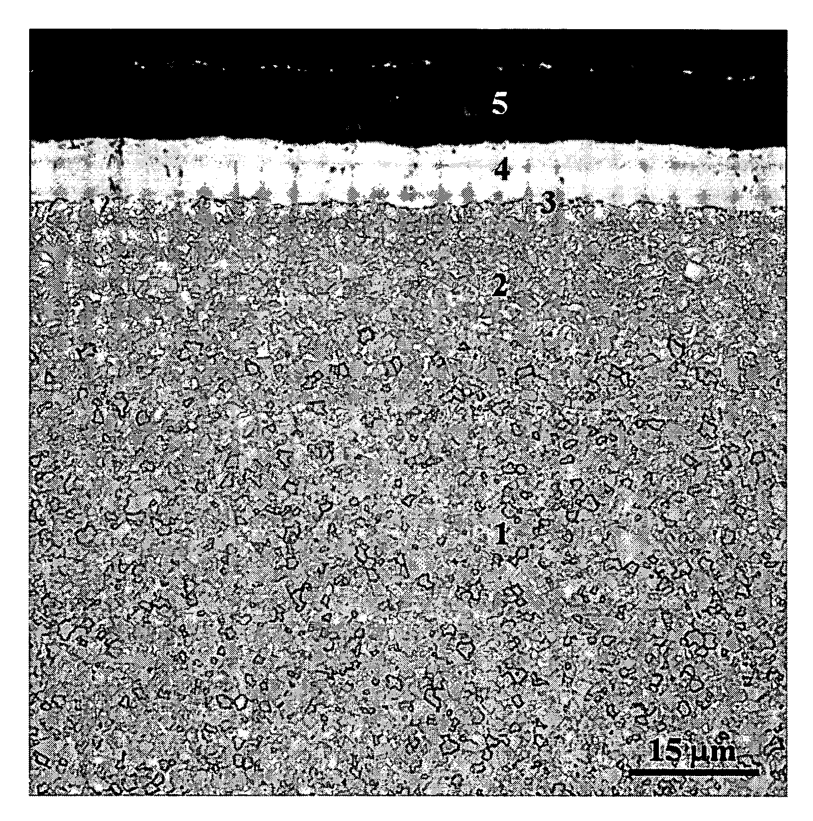
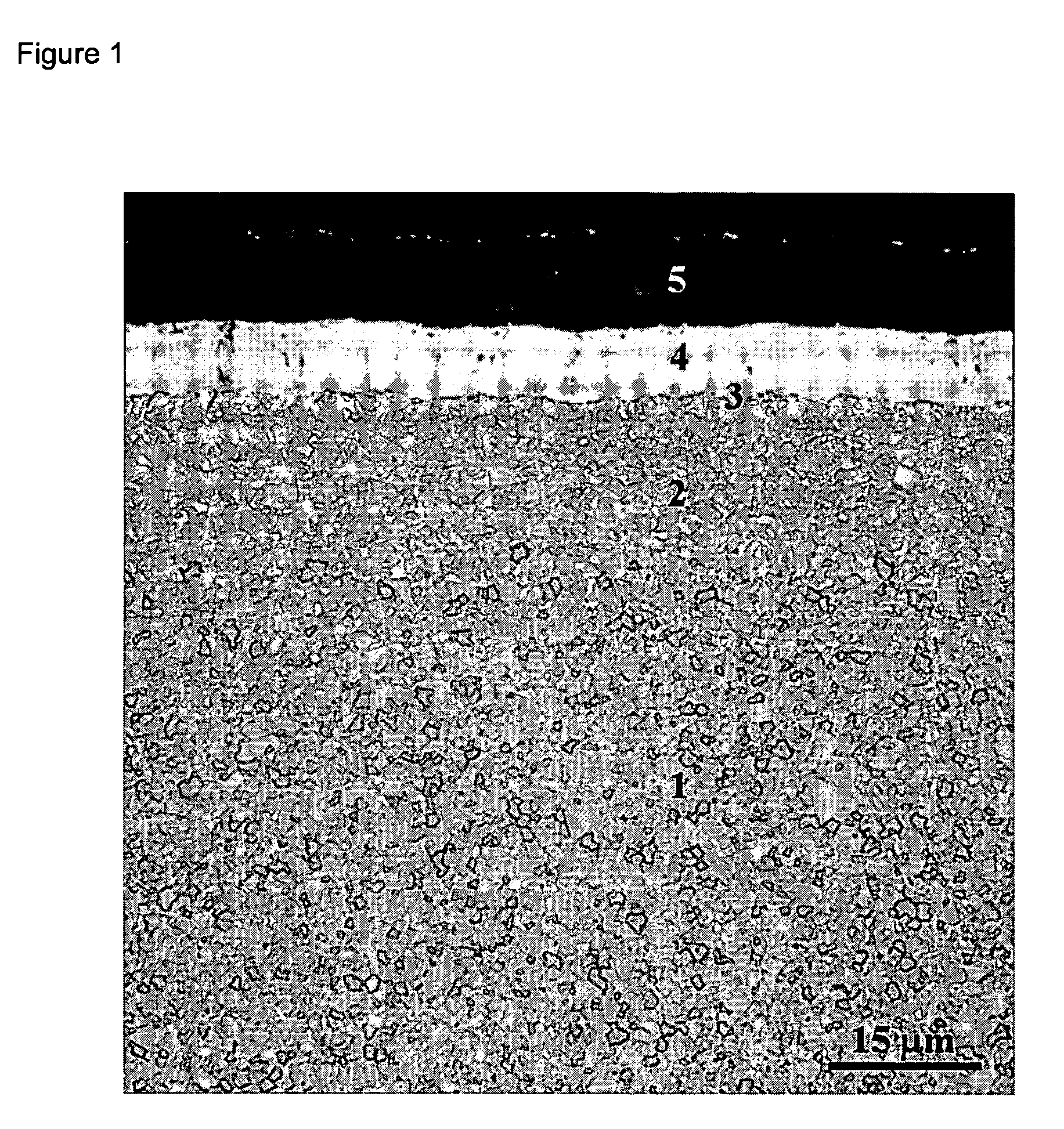
[0036]Grade A: A cemented carbide substrate in accordance with the invention with the composition 5.6 wt % Co, 1.5 wt % Ta, 0.9 wt % Nb, 1.5 wt % Ti, 5.98 wt % C, 0.08 wt % N, balance W, with a binder phase alloyed with W corresponding to an S-value of 0.91 was produced by conventional milling of powders, pressing of green compacts and subsequent sintering at 1430° C. Investigation of the microstructure after sintering showed that the mean intercept length of the tungsten carbide phase was 0.58 μm and that the surface zone of the inserts consisted of a 15 μm thick binder phase enriched part nearly free of cubic carbonitride phase. The substrate was coated in accordance with the invention with subsequent layers deposited during the same coating cycle. The first layer was a 0.2 μm thick TiCxNyOz layer with z0.6, having equiaxed grains. The second layer was 6.8 μm of columnar TiCxNyOz deposited at 835–850° C. with acetonitrile as carbon and nitrogen source, yielding an approximated car...

example 2

[0048]Inserts according to Grade A, Grade C, and Grade D were tested in longitudinal turning of a grey cast iron. The plastic deformation resistance of the different grades was investigated and compared.

[0049]

Material:Grey cast iron, SS0125Insert type:CNMG120412-M5Cutting speed: 350 m / minFeed: 0.4 mm / rev.Depth of cut: 2.5 mmCoolant:NoTime in cut:  5 minResults:Edge depressionGrade A (Grade according to the invention)  25 μmGrade C (Coating according to the invention)  30 μmGrade D (Coating according to the invention)  25 μm

[0050]As is shown in this test, the plastic deformation resistance of Grade A is not impaired by the presence of the Co enriched cubic carbonitride free surface zone.

example 3

[0051]Grade E: A conventional cemented carbide substrate designed for steel machining, with composition 5.5 wt % Co, 3.3 wt % Ta, 2.1 wt % Nb, 2.0 wt % Ti, 6.0 wt % C, 0.2 wt % N and balance W was combined with a coating according to Grade A (according to the invention). The substrate of the cutting tool had a 25 μm deep surface zone essentially free of cubic carbonitride phases, an average binder phase alloyed with W corresponding to an S-value of 0.85, and a mean intercept length of the WC in the sintered body of 0.73 μm.

[0052]Grade F: A commercial cemented carbide grade for cast iron machining in which a substrate according to Grade C is combined with a coating consisting of: a first thin layer of TiCxNyOz; a second layer of columnar TiCxNyOz with thickness 6.2 μm; a 2.1 μm thick layer of α-Al2O3; and an outermost 1.2 μm thick N-rich TiCxNyOz layer.

[0053]Inserts according to Grade A, Grade C, Grade E and Grade F were tested in roughing of a grey cast iron component. The component...


PUM

PropertyMeasurementUnit
thicknessaaaaaaaaaa
thicknessaaaaaaaaaa
thicknessaaaaaaaaaa

Abstract

The present invention relates to a coated cemented carbide cutting tool insert particularly useful for turning of cast irons but also low alloyed steels at mediate to high cutting speeds. The cutting tool insert is characterised by a cemented carbide body comprising WC, cubic carbonitrides, a W-alloyed Co binder phase, a surface zone of the cemented carbide body that is binder phase enriched and nearly free of cubic carbonitride phase, and a coating including an innermost layer of TiCxNyOz with equiaxed grains, a layer of TiCxNyOz with columnar grains and at least one layer of Al2O3.

Description

BACKGROUND OF THE INVENTION[0001]The present invention relates to a coated cemented carbide cutting tool insert particularly useful for turning of cast irons, but which can also be used to cut low alloyed steels at medium to high cutting speeds. The insert has a body with WC and cubic carbonitrides as hard phases, cemented with a tough Co binder phase, and a coating with high wear resistance. The insert is produced such that the surface zone of the body is of a different elemental composition than the bulk composition, yielding good wear resistance, plastic deformation resistance and edge strength simultaneously, which results in extended tool life for different machining conditions.[0002]Today, coated cemented carbide inserts with binder phase enriched surface zones are used for machining of steel and stainless steel materials. In these medium to coarse WC grained cutting tool materials, with relatively large additions of cubic carbonitride forming elements, the binder phase enrich...

Claims


Application Information

Patent Timeline
Patent Type & Authority Patents(United States)
IPC IPC(8): B32B9/00C22C29/02C23C16/30C23C30/00
CPCC23C30/005Y10T428/265Y10T428/24975A01G27/06A01G9/021A01G9/042
Inventor LARSSON, ANDREASZACKRISSON, JENNI
Owner SECO TOOLS AB
Why Eureka
Try Eureka