Process for enhancing material properties and materials so enhanced

a technology of enhanced materials and properties, applied in the field of composite insulation materials, can solve the problems of increased brittleness, high cost, and high cost of best thermal insulation materials, and achieve the effects of reducing durability and strength of syntactic foam, overcoming the disadvantage of stiffness, and increasing flexibility

Inactive Publication Date: 2006-09-05
THE RES FOUND OF STATE UNIV OF NEW YORK
View PDF15 Cites 47 Cited by
  • Summary
  • Abstract
  • Description
  • Claims
  • Application Information

AI Technical Summary

Benefits of technology

[0013]The present invention overcomes the disadvantage of stiffness by adding a stress relief pattern to one or both surfaces of the syntactic foam. The stress relief pattern can include one or more arrays of incisions and / or indentations formed in the syntactic foam. In one embodiment of this invention, the relief pattern is incorporated by cutting and / or indenting either completely or partially through one or both surfaces of the syntactic foam without materially removing a significant amount of material. In another embodiment, material is removed and replaced with the same (and / or another) material, but the replaced material may or may not be securely affixed. Rather the replaced material can be “free-floating.” The incisions and / or indentations increase the flexibility and decrease the durability and strength of the syntactic foam. Laminating a suitably stretchable and durable material to one or both sides of the stress-relieved syntactic foam compensates for the attendant loss of durability and strength of the syntactic foam caused by the incisions and / or indentations.
[0014]The materials produced by the present invention have numerous advantages relative to the current state of the art, including the following advantages: (1) enhanced material properties, such as improved flexibility; (2) retained desirable properties; (3) waterproof; (4) essentially incompressible; (5) excellent abrasion resistance; and (6) lower durometry than unprocessed syntactic foam.

Problems solved by technology

A classic example is that strong materials are typically heavy.
Another example is that the best thermal insulators (e.g., solid aerogels) are typically rigid, fragile, and have attendant low density.
A classic example is heat treating metals to increase hardness, usually at the expense of increased brittleness.
Thus, it is well known that one specific material does not typically possess all of the desired and / or required characteristics for a particular application.
For example, high strength is often at the expense of high weight, high density, high rigidity and incompressibility.
Another example is thermal insulation, which has low thermal conductivity, typically at the expense of compressibility; which, in turn, lowers its effective thermal resistance.
There usually remain, however, undesirable “side-effects” (design trade-offs).
However, as a diver goes to increasing depth in water, the associated and inevitable increase in local hydrostatic pressure compresses the gas trapped in the closed internal cells.
This reduces their volume and the foamed neoprene is said to “go flat.” Since the thermal resistance is the thickness divided by the thermal conductivity, this causes dual disadvantages inasmuch as its thickness is reduced and its effective thermal conductivity is increased.
This is done, however, at the expense of increased stiffness.
This increased stiffness is a distinct disadvantage of syntactic foam in that it does not conform well to contours, unless it is molded-in-place.
Furthermore, as the volume fraction of lower conductivity inclusions is increased, to increase its insulation capability, current syntactic foam suffers from a decrease in flexibility.
This makes it unsuitable for insulation when flexibility is required—such as for: insulating contours, clothing and underwater diver thermal protection.
Currently, the stiffness of syntactic foam makes it impractical for use in garments such as dive suits.

Method used


Image

  • Process for enhancing material properties and materials so enhanced
  • Process for enhancing material properties and materials so enhanced
  • Process for enhancing material properties and materials so enhanced

Examples


example 1

Selection of Materials for Development of a Hybrid Thermal Insulation for Use in Deep Sea Diving Suits

[0073]The current insulation used in NAVY diving, foamed neoprene, is a closed cell elastomeric foam. This insulation does not have sufficient thermal resistance for use in deep water. In particular, when this insulation is exposed to hydrostatic pressures of 350 feet of sea water, it compresses 70 percent. Due to this compressibility, the volume fraction of gas present in the foam insulation decreases 70 percent, thereby increasing the thermal conductivity by 200 percent. This change in thickness and thermal conductivity decreases the thermal resistance of the insulation (ratio of thickness to thermal conductivity) by 84 percent.

[0074]To overcome this inherent material flaw, various different materials have been and are being investigated to develop a new insulating material for divers. Along with the desirable thermal characteristics, the new insulation should also be flexible, st...

example 2

Testing of Effective Thermal Conductivity of ASPEN™ Aerogel Blanket Under Hydrostatic Loading

[0085]The total thermal conductivity can be expressed by the sum of three components: solid conductivity through the porous silica gel matrix, radiation through the voids, and conduction through the gas (Hrubesh et al., “Thermal Properties of Organic and Inorganic Aerogels,”J. Mater. Res. 9(3):731–738 (1994), which is hereby incorporated by reference in its entirety). Due to the high porosity of aerogel the solid conductivity can be a factor of 500 times lower than in non-porous silica (Scheuerpflug et al., J. Phys D: Appl. Phys. 24:1395 (1991), which is hereby incorporated by reference in its entirety). The solid conductivity can thus be approximated to be proportional to the density in the following way

ks∝ρα  (4)

where α≈1.5 in the density range ρ=70–300 kg / m3 (Lu et al., “Thermal Transport in Organic and Opacified Silica Monolithic Aerogels,”Journal of Non-Crystalline Solids 145:207–210 (1...

example 3

A New Hybrid Laminated Tenderized Syntactic Foam / Encapsulated Aerogel Insulation

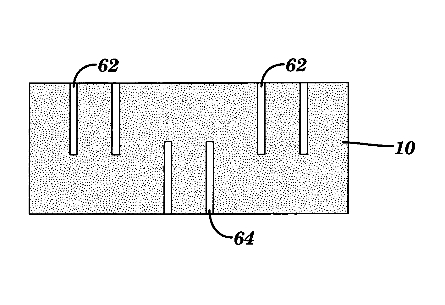
[0089]One embodiment of the composite insulation material of the present invention contains a layer of syntactic foam and an arrangement of circular aerogel blanket pieces embedded between the syntactic foam and the outermost laminations of a durable, flexible, stretchable material such as spandex. Syntactic foam is made from a suitable matrix (e.g., two-part silicone) and a suitable filler (e.g., microspheres) and plasticizers.

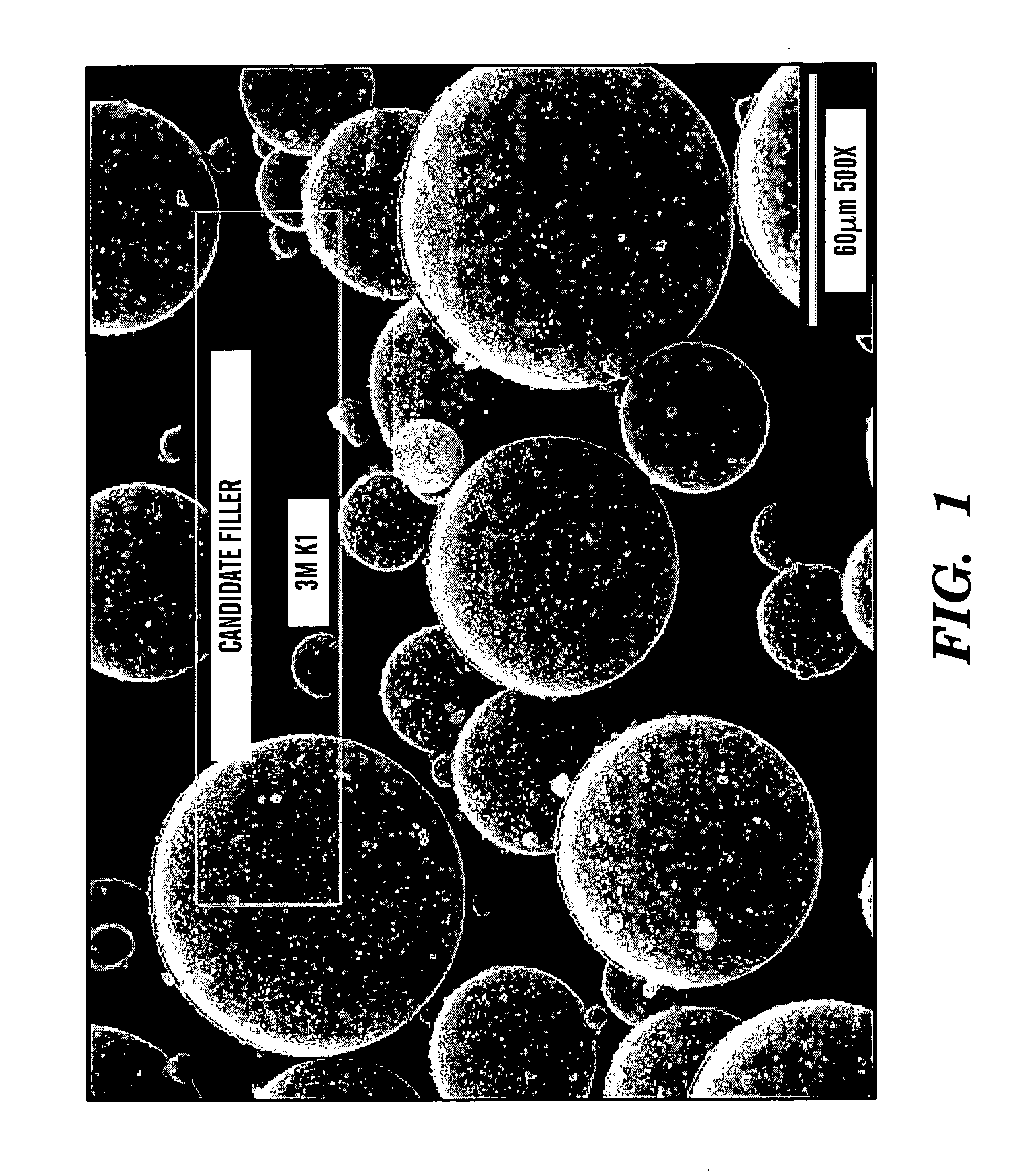
[0090]Syntactic foam was made by manually weighing and mixing the following components, per preferred formulation: silicone rubber components; plasticizer; and microsphere glass beads. The mixture was then evacuated (prior to cure) in a chamber to remove entrained air by reducing the chamber pressure by about 27″ Hg vacuum for a period of about 20 minutes. As an example, the syntactic foam may have the following components: (1) filler (e.g., 40% by volume 3M K1 microspheres); and / ...


PUM

PropertyMeasurementUnit
diameteraaaaaaaaaa
thicknessaaaaaaaaaa
thicknessaaaaaaaaaa

Abstract

The present invention relates to a composite insulation material. The composite insulation material includes a syntactic foam component and a plurality of aerogel inserts. The present invention also relates to a method of making a composite insulation material. The present invention further relates to a method for enhancing the flexibility of a solid material.

Description

[0001]This application claims the benefit of U.S. Provisional Patent Application Ser. No. 60 / 405,094, filed Aug. 21, 2002, which is hereby incorporated by reference in its entirety.[0002]The subject matter of this application was made with support from the United States Government under the Office of Naval Research (ONR), Grant No. N00014-02-1-0278. The U.S. Government may have certain rights.FIELD OF THE INVENTION[0003]The present invention relates to a composite insulation material, a method for making the composite insulation material, and products that contain the composite insulation material. The present invention also relates to a method for enhancing the flexibility of a solid material, and a solid material so enhanced by the method.BACKGROUND OF THE INVENTION[0004]It is rare that a single material will have all (or even several) of the typically desired characteristics for a particular application. A classic example is that strong materials are typically heavy. Another exam...

Claims


Application Information

Patent Timeline
Patent Type & Authority Patents(United States)
IPC IPC(8): B32B3/12B29C47/00B63C11/04F16L11/00B29C48/00B32B3/00B32B5/18B32B27/18C08J9/00C08J9/32C08J9/35
CPCB32B5/18B32B27/18C08J9/0066C08J9/32C08J9/35C08J2383/04Y10T428/139Y10T156/1064Y10T428/24479Y10T428/24496Y10T156/1026Y10T428/24273Y10T428/24314F17C2203/0325Y10T428/249969B32B1/08B32B7/12B32B25/045B32B25/08B32B25/14B32B27/065B32B27/08B32B27/20B32B27/34B32B2307/102B32B2307/206B32B2307/304B32B2307/7265B32B2319/00B32B2377/00B32B2597/00
Inventor MOLLENDORF, JOSEPH C.PENDERGAST, DAVIDBARDY, ERIK R.SAMIMY, SAWSONSTIMSON, ERIC M.DAURIA, COLIN K.BUCHNER, RAYMOND D.
Owner THE RES FOUND OF STATE UNIV OF NEW YORK
Why Eureka
Try Eureka