Optical semiconductor device with multiple quantum well structure

a semiconductor device and quantum well technology, applied in the direction of individual semiconductor device testing, semiconductor lasers, instruments, etc., can solve the problems of reducing internal quantum efficiency, affecting the injection behavior, and increasing forward voltage, so as to reduce the quality of the deposited layer, reduce the quantum efficiency, and reduce the stability.

Inactive Publication Date: 2006-09-12
OSRAM OLED
View PDF21 Cites 70 Cited by
  • Summary
  • Abstract
  • Description
  • Claims
  • Application Information

AI Technical Summary

Benefits of technology

[0012]The particular advantage of the step-by-step increase in the In content is that a potential profile resembling a delta potential is produced, in particular in the case where the thickness of the single layers does not significantly exceed that of a monolayer. The difference in the energy level in the barrier layers and the energy level obtained for one electron in the well layer is consequently not greater than in the case of a rectangular well layer with a significantly lower indium content as the uppermost single layer of the stepped well layer. This achieves the effect that the advantages of a reduced overall indium content are retained, but the strain is at the same time influenced by the high indium content of the last single layer in such a way that the nucleation of InGaN-rich phases is improved and, consequently, the quantum efficiency is increased.
[0013]A further advantage arises for the following reason: the epitaxial growth of indium-containing III-V semiconductors (for example InGaAs, InGaN) is made more difficult by the relatively great atom radius of the indium. With constant fluxes of the group III components, indium is therefore incorporated with a delay. The indium concentration increases during the growth and approaches an equilibrium value exponentially. During the enriching phase, a certain indium coverage is formed on the growth surface. Only when this coverage is achieved is a constant amount of indium incorporated into the crystal. If, however, too much indium is offered, the indium present on the surface forms metallic droplets, which reduce the quality of the deposited layers. In particular, however, such indium droplets produce shunts at the p-n junction, reducing not only the quantum efficiency but also the stability with respect to electrostatic discharging (ESD). These effects are reduced by initially depositing indium-containing layers with a low indium content, preferably less than 5%, then increasing the indium content in subsequent layers. In the case of the active layer itself, the substructure is then already prepared by the well layers in such a way that InGaN compositions with a higher indium content can be deposited.
[0014]The nucleation of indium-rich phases is advantageously improved by the increasing indium content in the well layer or layers. The harmful formation of indium droplets is at least considerably reduced.

Problems solved by technology

However, these quantum wells lead to a considerable increase in the forward voltage.
However, this adversely effects the crystal quality of the active layer or impairs the injection behavior and consequently reduces the internal quantum efficiency.

Method used


Image

  • Optical semiconductor device with multiple quantum well structure
  • Optical semiconductor device with multiple quantum well structure
  • Optical semiconductor device with multiple quantum well structure

Examples


Embodiment Construction

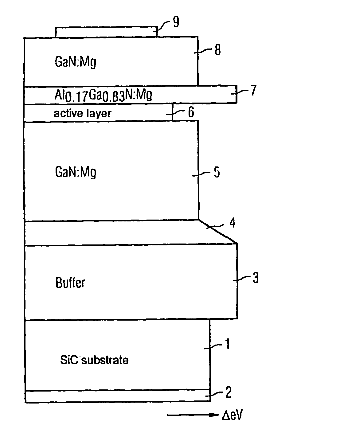
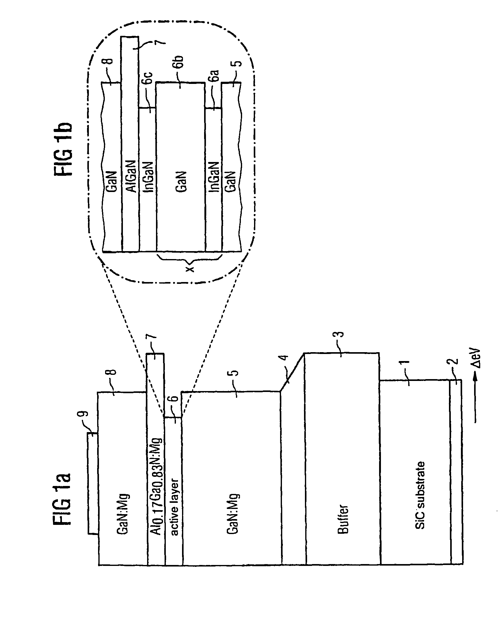
[0021]According to FIG. 1a, initially a buffer layer 3 of aluminum-gallium-nitride (AlGaN) is formed on a substrate 1 of silicon carbide (SiC), to which a first contact electrode 2 is connected. This is followed by a further layer 4 of aluminum-gallium-nitride. A further buffer layer 5 of silicon-doped gallium nitride is arranged over the layer 4 and the quantum well structure 6a, b, still to be explained in more detail, is arranged over that, followed by the actual active layer 6c. Arranged over the active layer 6 is a further layer 7 of aluminum-gallium-nitride, which serves as an electron barrier. This layer 7 is preferably doped with magnesium. A further GaN layer, not designated, may be arranged between the layers 6 and 7. A gallium-nitride layer 8, on which a second contact electrode 9 of the device is provided, is arranged over the layer 7.

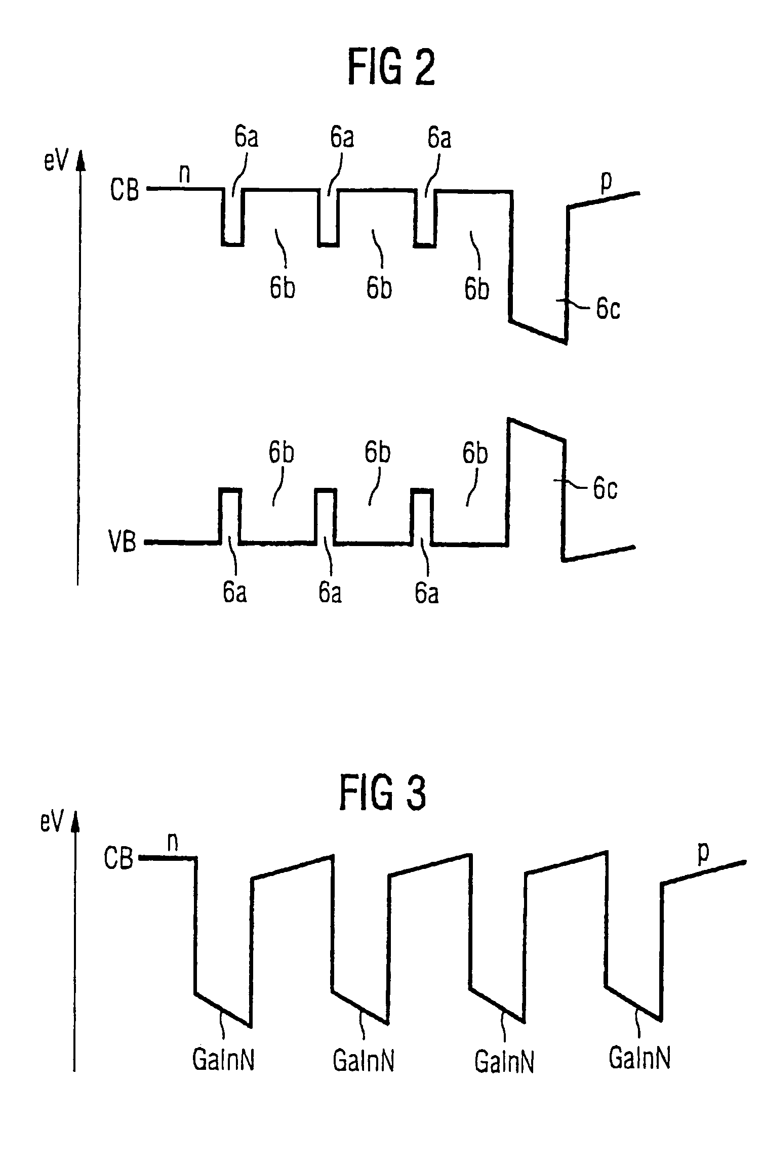
[0022]The right-hand side of the layer structure shows in a schematically indicated manner the band gap of the single layers between the v...


PUM


Abstract

An optical semiconductor device with a multiple quantum well structure, in which well layers and barrier layers comprising various types of semiconductor layers are alternately layered, in which device well layers (6a) of a first composition based on a nitride semiconductor material with a first electron energy and barrier layers (6b) of a second composition of a nitride semiconductor material with electron energy which is higher in comparison with the first electron energy are provided, followed, seen in the direction of growth, by a radiation-active quantum well layer (6c), for which the essentially non-radiating well layers (6a) and the barrier layers (6b) arranged in front form a superlattice.

Description

CROSS REFERENCE TO RELATED APPLICATIONS[0001]Pursuant to 35 U.S.C. § 120, this application continued claims the benefit of prior U.S. application Ser. No. 09 / 913,394, filed Feb. 5, 2002 U.S. Pat. No. 6,849,881 which is a National Phase Application for International Application No. PCT / DE00 / 04089, filed Nov. 20, 2000, which claims priority to German patent application 19955747.0, filed Nov. 19, 1999.FIELD OF THE INVENTION[0002]The invention relates to an optical semiconductor device with a multiple quantum well structure, in which well layers and barrier layers comprising various types of semiconductor layers are alternately layered.BACKGROUND OF THE INVENTION[0003]A device of this type is known for example from EP 0 666 624 B1 or from Journal of Crystal Growth 189 / 190 (1998) pages 786–789.[0004]The high quantum efficiency of indium-gallium-nitride (InGaN)-based LEDs and laser diodes is caused by the self-organized growth of indium-rich islands in the active quantum well. As a result...

Claims


Application Information

Patent Timeline
Patent Type & Authority Patents(United States)
IPC IPC(8): G01R31/00G01R31/26G01R31/28H01L33/06H01L33/32H01S5/34H01S5/343
CPCB82Y20/00H01L33/06H01S5/34333H01L33/32H01S5/3407H01S5/3408
Inventor HARLE, VOLKERHAHN, BERTHOLDLUGAUER, HANS-JURGENBOLAY, HELMUTBADER, STEFANEISERT, DOMINIKSTRAUSS, UWEVOLKL, JOHANNESZEHNDER, ULRICHLELL, ALFREDWEIMER, ANDREAS
Owner OSRAM OLED
Why Eureka
Try Eureka