Apparatus and process used in growing crystals

a technology of crystal growth and apparatus, applied in the field of new crystal growth apparatus, can solve the problems of large changes in psd, difficult to predict the psd of the produced crystals, and inability to even anticipate these psd changes

Inactive Publication Date: 2006-10-17
DUPONT POLYMERS INC
View PDF12 Cites 5 Cited by
  • Summary
  • Abstract
  • Description
  • Claims
  • Application Information

AI Technical Summary

Benefits of technology

[0020]Another embodiment of the invention involves (a) generating dislodged crystals according to the process described above; (b) mixing the first saturated solution and dislodged crystals with a second saturated solution to form a third saturated solution; (c) treating the third saturated solution to form a supersaturated solution; and (d) passing the supersaturated solution of step (c) through a growth zone for a predetermined time to grow the dislodged crystals to a desired size under conditions of plug flow; and (e) separating the dislodged cry

Problems solved by technology

Therefore, slight changes in process conditions can cause large changes in PSD.
Moreover, it has been difficult to predict the PSD of the produced crystals; so it is often impossible to even anticipate these PSD changes.
However, seeding is often poorly managed, awkward, and even dangerous.
In practice, it may happen that the heel completely dissolves, leaving no seed whatsoever for the subsequent batch.
Furthermore, leaving the heel in the vessel decreases (often substantially) the capacity of the process.
This is labor-intensive and hard to manage at best.
In addition, special equipment may be necessary, particularly when flammable or toxic solvents are used.
The above problems exist in both continuous and batch processes.
Although conventional continuous crystallization processes are inherently “self-seeded” because there is always a crop of crystals present after initial start-up, there is little control over crystal form.
Furthermore, the concentration of crystals in the vessel is typically not controlled.
Therefore, while growing, the particles are subject to attrition and breakage for different lengths of time.
In addition, the use of continuous crystallizers has been largely limited to large volume products because of the cost of installing a continuous process

Method used


Image

  • Apparatus and process used in growing crystals
  • Apparatus and process used in growing crystals
  • Apparatus and process used in growing crystals

Examples


example 1

Production of Very Small Uniform Crystals Suitable for Use as Seed Crystals Produced in Nuclei Generator

[0076]The prototype nuclei generator shown in FIG. 2 and in cross-section in FIG. 3 was employed. A thin (0.035″ / 0.889 mm) sheet of stainless steel was used as the nucleating surface (separating the solution and cooling chambers). The area of the sheet was 26 cm2. An aqueous solution of adipic acid was prepared at 32 g / L adipic acid, corresponding to the saturation concentration at 35° C. Water at 5° C. was circulated through the cooling chamber from a constant temperature / circulator bath. The adipic acid solution was pumped through the nuclei generator with a peristaltic pump at 50 mL / min. Pulsed 20 kHz ultrasound was applied to the cooling chamber side of the nucleation surface from an ultrasonic horn driven by a Dukane 1000 Autotrac controller and transducer (Dukane Corporation, St. Charles, Ill.) operated at 40% power, nominally 400 watts. A 2 sec ultrasound pulse was applied ...

example 2

Tubular Nucleation Zone

[0078]In another embodiment of the “nuclei generator”, a 24 inch length of ¼ inch outer diameter, ⅛ inch inner diameter polyethylene tube was immersed in an ultrasonic bath (Crest Trusweep Genesis, Crest Ultrasonics, Trenton, N.J.) filled with water maintained at 5° C. with a refrigerated circulator bath. Aqueous adipic acid solution at a concentration of 32 g / L, initially at 37° C., was pumped through the tubing with a peristaltic pump at a flow rate of 50 mL / min. In previous chilled tube experiments, significant crystal deposition on the tube inner wall was observed. When the exterior of the immersed tube is subjected to pulsed ultrasound in the ultrasonic bath (2 sec pulse every 30 sec), however, no crystal deposition is observed on the inner tube wall. A suspension of uniform small particles is collected. Sampling the particles on a hydrophobic surface, as described above, would show very uniform small particles approximately 10 μm in size.

example 3

Nuclei Generator Coupled With Crystal Growth Zone to Produce Very Uniformly Sized Crystals

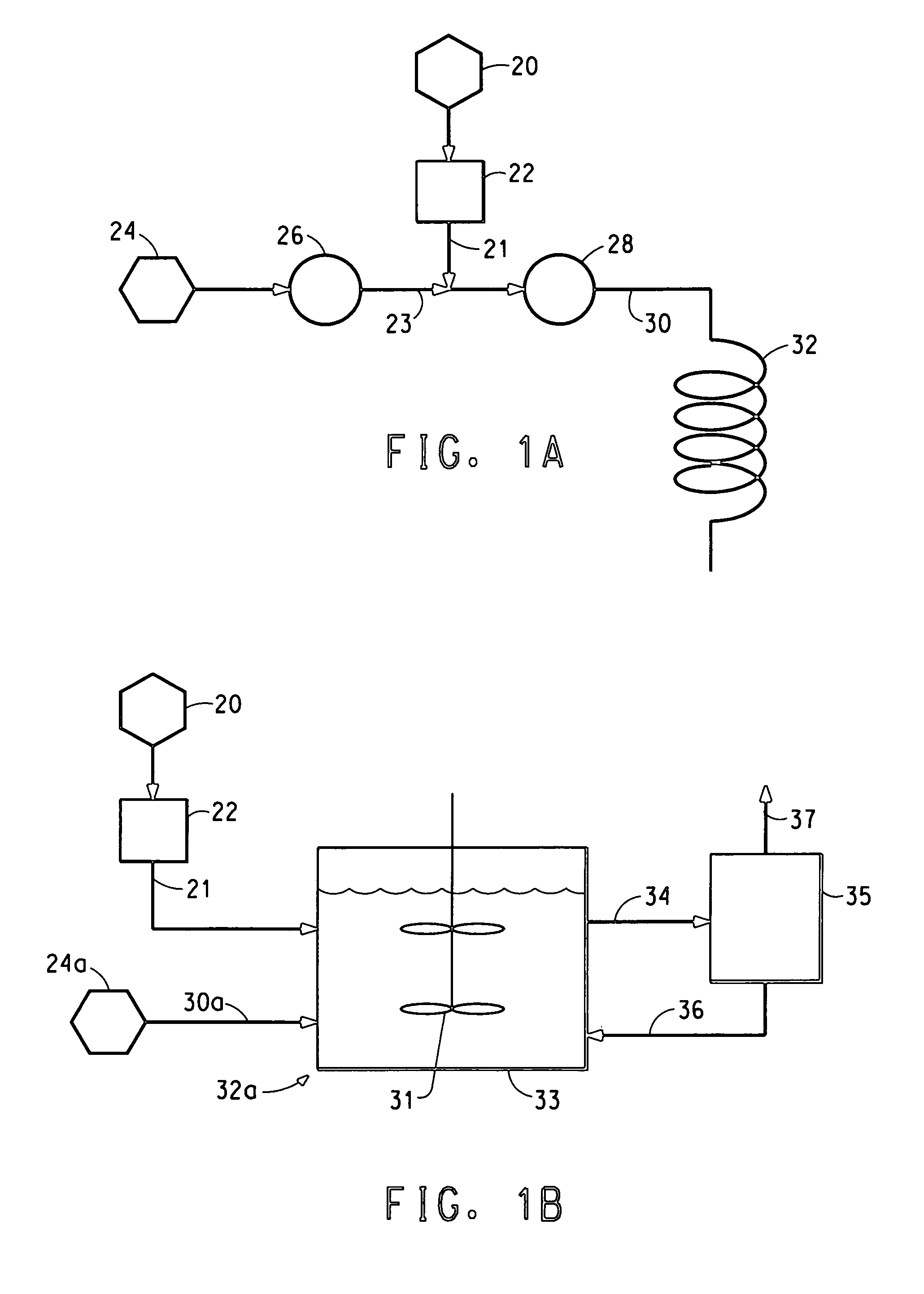
[0079]Adipic acid solution, 32 g / L (corresponding to saturation at 35° C.), was fed to the prototype nuclei generator (described in Example 1) at 54.5 mL / min and 37° C. Cooling water was fed to the nuclei generator at 5° C. Ultrasound was applied for a 2 sec pulse every 15 sec; power at 40%. The nucleation surface was clean polyethylene. The exit temperature measured for the solution flowing through the nuclei generator was approximately 29.3° C. This corresponds to a maximum dimensionless supersaturation, σmax=0.28, where σmax=(co−ceq29.3° C.) / ceq29.3° C., co is the inlet concentration, and ceq29.3° C. is the equilibrium or saturation concentration at the exit of the nuclei generator.

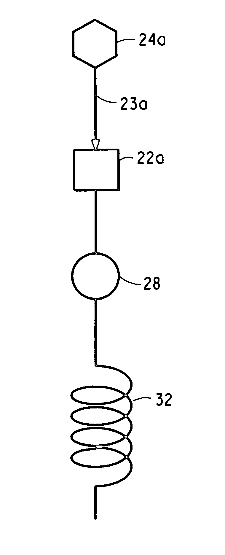
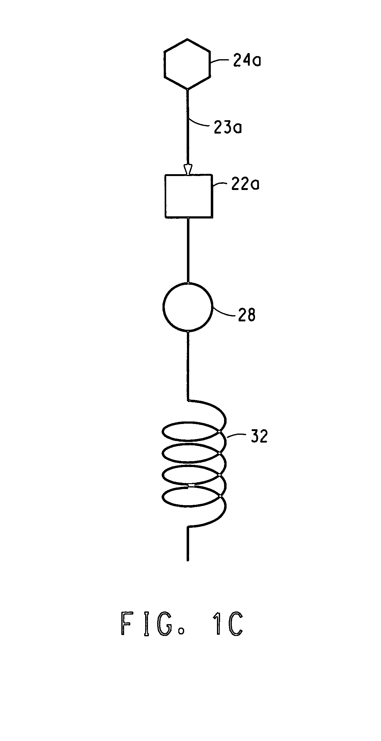
[0080]The stream of solution and small crystals issuing from the nuclei generator was then fed to a simple “growth zone”. In this embodiment, the growth zone was a 28.5 m coil of 3 mm (inside diameter) polyethylen...


PUM

PropertyMeasurementUnit
Thicknessaaaaaaaaaa
Widthaaaaaaaaaa
Gravityaaaaaaaaaa

Abstract

This invention relates to a novel system for making uniform crystals. The system, by virtue of the nature of its crystal product, is useful in various chemical, pharmaceutical, agricultural, and biotechnology applications. The invention features physically separated and controlled crystal nucleation and growth zones useful in industrially scaled crystallization processes. The invention also provides a method to preferentially nucleate and crystallize a desired category of crystal structure (enantiomer, solvate, polymorph) of non-chiral and chiral compounds.

Description

CROSS-REFERENCE TO RELATED APPLICATIONS[0001]This application claims the benefit of U.S. Provisional Application Ser. No. 60 / 369,664, filed Apr. 2, 2002. FIELD OF THE INVENTION[0002]This invention relates to a novel system for making uniform crystals. The system, by virtue of the nature of its crystal product, is useful in various chemical, pharmaceutical, agricultural, and biotechnology applications. The invention features the use of physically separated and controlled crystal nucleation and growth in industrial crystallization processes.BACKGROUND[0003]High quality crystals are of great value for a variety of industrial and research applications. The ability to obtain a more tightly controlled particle size distribution as well as consistent and controlled crystal habit (shape) and structure (e.g., polymorph) is highly sought after, particularly in the biotechnology and pharmaceutical industries.[0004]Crystallization is conventionally carried out in agitated tanks to which dissolv...

Claims


Application Information

Patent Timeline
IPC IPC(8): C30B7/08B01D9/02B01D9/00C07C227/34C07C229/08C30B7/00
CPCB01D9/0013B01D9/0081B82Y30/00C30B7/00B01D9/0018B01D9/005C30B29/54
Inventor GREEN, DANIEL ALBERT
Owner DUPONT POLYMERS INC
Why Eureka
Try Eureka