Encoded variable filter spectrometer

a variable filter and optical spectrometer technology, applied in the field of optical spectrometers, can solve the problems of large and relatively expensive large cost of micropac assemblies b>10/b> that can be used in visible and/or very near infrared regions, and reduce the complexity of the system, increase the signal-to-noise ratio of the system, and optimize optical throughput

Inactive Publication Date: 2006-10-24
RIO GRANDE MEDICAL TECH
View PDF199 Cites 19 Cited by
  • Summary
  • Abstract
  • Description
  • Claims
  • Application Information

AI Technical Summary

Benefits of technology

[0014]The present invention provides a spectrometer capable of being incorporated into a small, simple, rugged, inexpensive spectroscopic system for commercial applications. The spectrometer of the present invention optimizes optical throughput, increases the signal-to-noise ratio of the system, and decreases the complexity of the system. The spectrometer of the present invention is well suited for incorporation in a spectroscopic system that collects data necessary to perform spectroscopic determinations on biological media. Spectroscopic determinations include measuring th

Problems solved by technology

In addition, the spectroscopic system must be rugged to withstand shock, dust, humidity and other adverse environmental influences.
For example, in the case of using near-infrared spectra (1.25–2.5 μm) to measure analytes in biological media, Fourier Transform instruments that provide high optical throughput, high stability, high versatility and are readily available tend to be large and relatively expensive.
The cost of the MicroPac assembly 10 that can be used for visible and/or very near infrared regions is significantly affected by the price of t

Method used


Image

  • Encoded variable filter spectrometer
  • Encoded variable filter spectrometer
  • Encoded variable filter spectrometer

Examples


Embodiment Construction

[0036]The following detailed description should be read with reference to the drawings in which similar elements in different drawings are numbered the same. The drawings, which are not necessarily to scale, depict illustrative embodiments and are not intended to limit the scope of the invention.

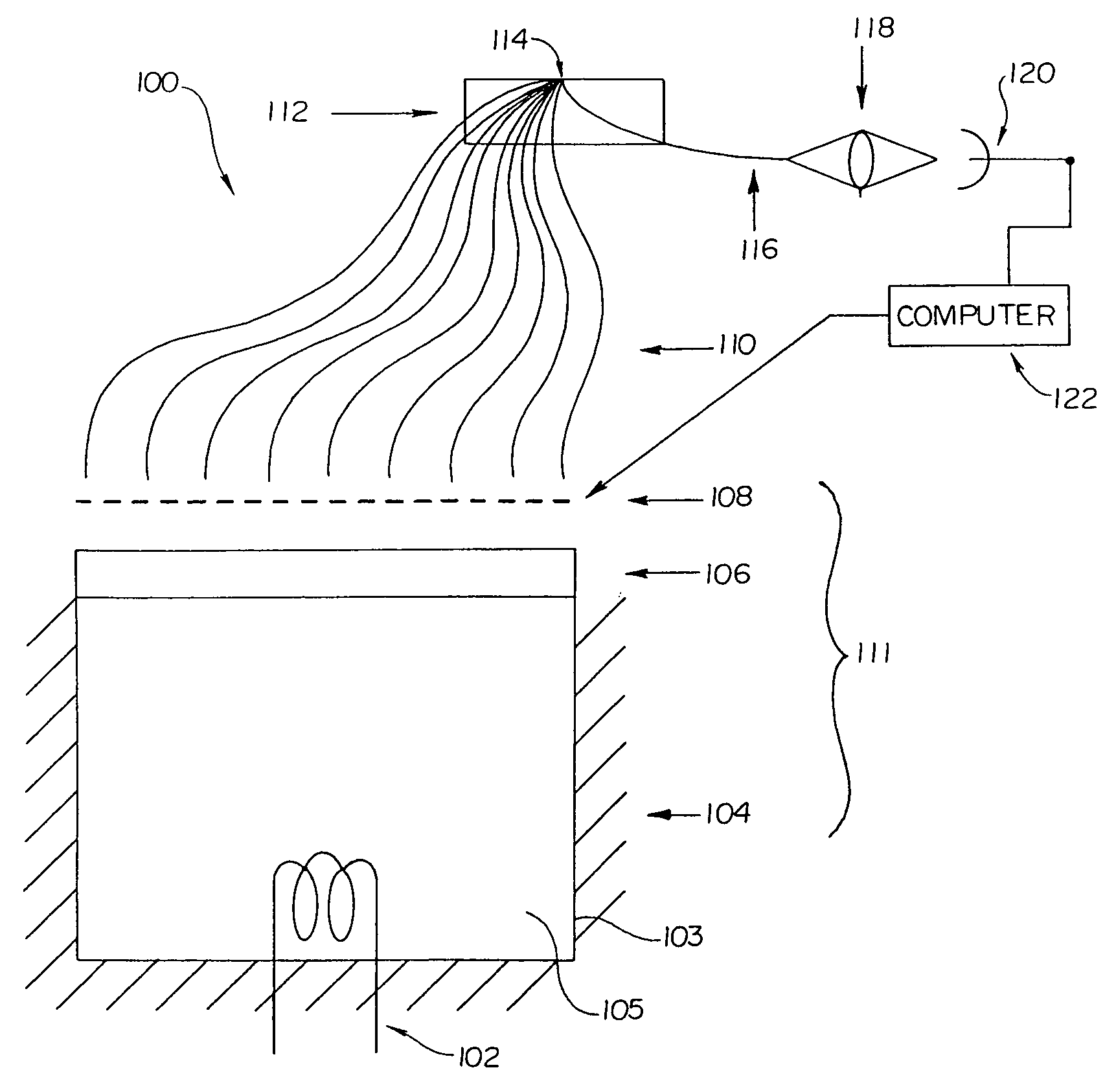
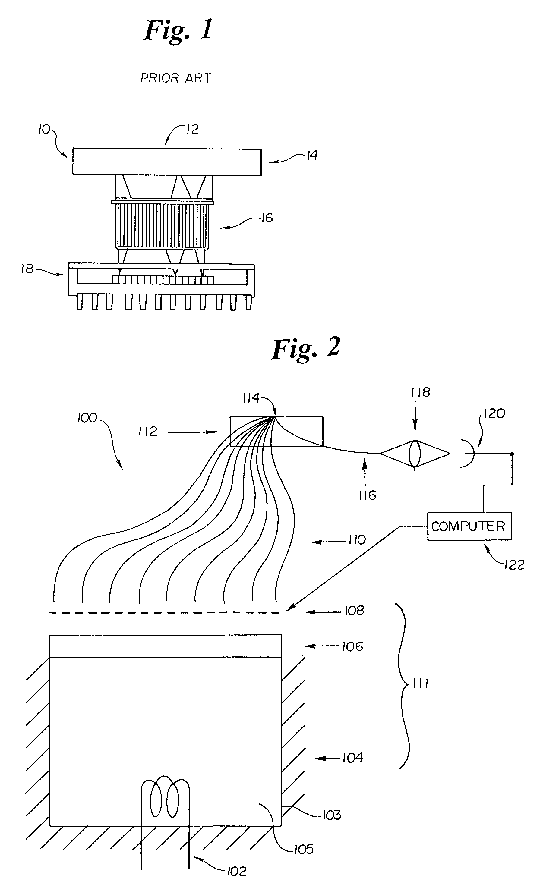
[0037]Refer now to FIG. 2, which is a schematic illustration of a spectrometer system 100 utilizing a basic encoded variable filter (EVF) device 111 in accordance with an embodiment of the present invention. Note that spectrometer components 106 / 108 are collectively referred to as encoded variable filter (EVF) device or unit 111. Further, component 104, the integrating chamber, is an optional component included in encoded variable filter device 111. The spectrometer 100, in a preferred embodiment, includes an optical light source 102, an optical integrating chamber 104, a filter assembly 106 such as a linear variable optical bandpass filter, a spatial encoding device 108, a sampler 112 incor...


PUM


Abstract

Spectroscopic system and spectrometers including an optical bandpass filter unit having a plurality of bandpass regions and a spatial encoding unit for encoding discrete frequencies of light passing through the optical filter. The incorporation of the encoding unit allows the spectrometer system to use a detector having one or a small number of elements, rather than using a more expensive detector array typically used with filter-based spectrometers. The system can also include an integrating chamber that collects the light that is not transmitted through the bandpass filter unit, and redirects this light to strike the filter unit again, resulting in a significant increase in the optical power passing through the filter. The integrating chamber maximizes the return of the reflected light to the filter assembly and minimizes optical losses. The integrating chamber may be an orthogonal design to preserve the optical geometric characteristics of the light entering the chamber.

Description

RELATED APPLICATIONS[0001]This application is related to U.S. patent application Ser. No. 09 / 832,585, entitled “System for Non-Invasive Measurement of Glucose in Humans”; U.S. patent application Ser. No. 09 / 832,586, entitled “Illumination Device and Method for Spectroscopic Analysis”; and U.S. patent application Ser. No. 09 / 832,608, entitled “Optically Similar Reference Samples and Related Methods for Multivariate Calibration Models Used in Optical Spectroscopy”, all filed on the same date herewith and assigned to the assignee of the present application. The disclosure of each of these related applications is hereby incorporated by reference.FIELD OF THE INVENTION[0002]The present invention generally relates to optical spectrometers. More specifically, the present invention relates to encoded filter-based optical spectrometers.BACKGROUND OF THE INVENTION[0003]Optical spectrometers are systems that permit the measurement of optical intensity at specific wavelengths within a spectral ...

Claims


Application Information

Patent Timeline
IPC IPC(8): G01J3/04G01J3/10G01J3/12G01J3/32G01N21/25
CPCG01J3/10G01J3/32G01N21/255G01J3/12G01J3/0218G01J2003/123G01J2003/1234
Inventor ROWE, ROBERT K.ABBINK, RUSSELL E.CORCORAN, STEPHAN P.
Owner RIO GRANDE MEDICAL TECH
Why Eureka
Try Eureka