
Surfacing of metal fluoride excimer optics

a technology of excimer optics and metal fluoride, which is applied in the field of improved coating of optical elements, can solve the problems of material surface degradation, increased degradation, and increased degradation, and achieve enhanced chemical vapor deposition, high purity, and high purity silica

Active Publication Date: 2006-10-31
CORNING INC
View PDF7 Cites 27 Cited by
  • Summary
  • Abstract
  • Description
  • Claims
  • Application Information

AI Technical Summary

Benefits of technology

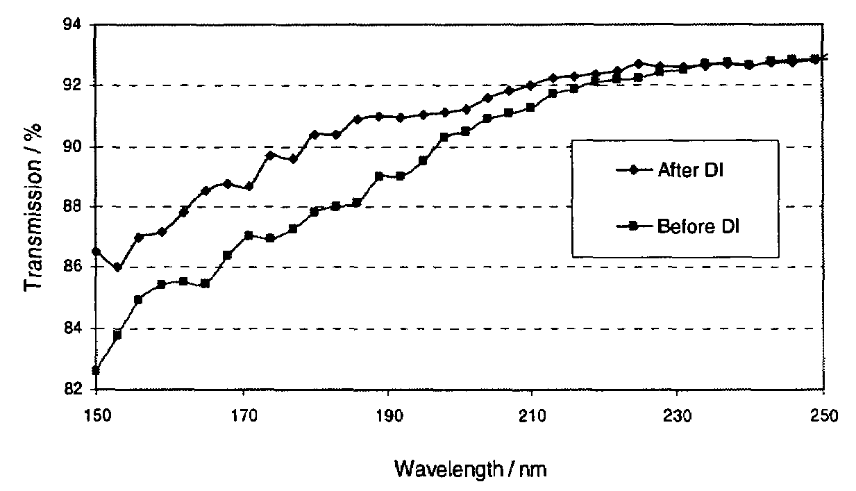
The solution significantly extends the lifespan of optical elements by reducing absorption and wavefront distortions, improving transmission performance, and enhancing resistance to laser-induced damage, thus meeting the demands of high-repetition-rate excimer laser systems.

Problems solved by technology

More recently, it has been noticed that there is optical window surface degradation in high peak and average power 193 nm excimer lasers using window materials made from substances other than silica.
It is a concern that such degradation will be more severe when existing optical materials are used in 157 nm laser systems.
While some solutions, for example, such as using MgF2 as the window or lens material for existing 193 nm laser systems have been proposed, it is believed that such materials will also experience surface degradation with time, leading to the requirement that the expensive windows be periodically replaced.
In addition, the use of MgF2 as a window material, while it might be successful from a mechanical viewpoint, presents a problem of color center formation that is detrimental to transmission performance of the laser beam.
However, crystals of CaF2 and the optical elements made from CaF2, are difficult to optically polish.
Furthermore, polished but uncoated surfaces of CaF2 are susceptible to degradation when exposed to powerful excimer lasers operating in the deep ultraviolet (“DUV”) range, for example at 248 and 193 nm and the vacuum ultraviolet (“VUV”) range, for example at 157 nm.
The cause of the damage is thought to be fluorine depletion in the top surface layers of the polished surface.

Method used


Image

  • Surfacing of metal fluoride excimer optics
  • Surfacing of metal fluoride excimer optics
  • Surfacing of metal fluoride excimer optics

Examples


Embodiment Construction

[0024]In the following description and in the Figures, CaF2 is used as the exemplary alkaline earth metal fluoride single crystal material that is made into a coated optical element in accordance with the invention. However, it should be remembered that the invention applies to all optical elements made of alkaline earth metal fluorides or elements made from mixtures of such alkaline earth metal fluorides. In addition, the invention applies to all optical element surfaces subjected to cutting, grinding and polishing; for examples the two faces of a laser window or lens.

[0025]The invention is directed to coated optical elements made from alkaline earth metal fluorides, and especially to coated optical elements made from calcium fluoride, CaF2, or a mixture of calcium fluoride with one or more other alkaline earth metal such as barium, magnesium or strontium; and to a method of making such elements. The optical elements according to the invention have improved transmission properties ...


PUM

PropertyMeasurementUnit
thicknessaaaaaaaaaa
wavelengthsaaaaaaaaaa

Abstract

The invention is directed to improved coated metal fluoride single crystal optical elements suitable for use in below 250 nm optical lithography, and particularly below 200 nm lithography. The coated elements of the invention can be lenses, windows, prisms and other elements used in lithographic methods, including the laser sources used therein. The invention is also directed to a method of removing the quasi-Bielby layer formed when a shaped optical element is polished. Removal of the quasi-Bielby layer prior to coating results in improved durability and optical transmission characteristics of the coated lenses. The coating material can be any material that does not impede the transmission of below 250 nm electromagnetic radiation. Fluorine doped silicon dioxide is the preferred coating material.

Description

FIELD OF THE INVENTION [0001]This invention is directed to improved coated optical elements that can be used for the transmission of below 250 nanometer (nm) electromagnetic radiation, and in particular to improved coated alkaline earth metal fluoride optical elements that thereby have greater durability and improved transmissivity for use in the area of optical lithography; and additionally to a method for making such optical elements.BACKGROUND OF THE INVENTION [0002]The use of high power lasers, for example, those with pulse energy densities (fluence) above 20 mJ / cm2, with pulse lengths in the low nanosecond range, can degrade the optics used in laser lithography systems. T. M. Stephen et al., in their article “Degradation of Vacuum Exposed SiO2 Laser Windows” SPIE Vol. 1848, pp. 106–109 (1992), report on the surface degradation of fused silica in Ar-ion laser. More recently, it has been noticed that there is optical window surface degradation in high peak and average power 193 n...

Claims


Application Information

Patent Timeline
Patent Type & Authority Patents(United States)
IPC IPC(8): B32B9/00
CPCG02B1/02G02B1/105G02B1/14G02B5/0278
Inventor MAIER, ROBERT LWANG, JUE
Owner CORNING INC
Learn More