Lithographic apparatus with debris suppression, and device manufacturing method

a technology of lithographic apparatus and debris, which is applied in the field of lithography, can solve the problems of damage to delicate reflectors and/or other elements, loss of beam intensity, and accumulation of absorbing layers on the surface of optical elements, and achieve the effect of removing undesirable contaminants

Inactive Publication Date: 2006-11-14
ASML NETHERLANDS BV
View PDF17 Cites 25 Cited by
  • Summary
  • Abstract
  • Description
  • Claims
  • Application Information

AI Technical Summary

Benefits of technology

[0009]It is an aspect of embodiments of the present invention to provide a simple device that may be used in a lithographic projection apparatus to remove undesirable contaminants (debris) produced by the radiation source.
[0012]The advantage of this solution is that, instead of using a complicated electron source or a plasma generation device (like by capacitive or inductive RF discharge or AC discharge), only an additional electrode has to be introduced in the apparatus, preferably positioned in the projection beam, and that, in a simple way, by using the electrons that are created by the source, an electron avalanche is created resulting in a ‘simple’ plasma that substantially suppresses and eliminates the introduction of debris to the rest of the apparatus. This way, the electrode is used to capture contaminant particles (debris) in the projection beam from the radiation source.
[0019]It can be helpful to improve the confinement of the electrons by positioning a magnetic field generator for applying an axial magnetic field, wherein the Lorentz force on moving electrons can help confine the electrons between the source and the additional electrode. This results in a higher electron and ion density in the volume between the radiation source and the electrode. In a further embodiment, the ionization effect by the electric field, between the additional electrode and the radiation source, can be improved by providing a magnetic field generator applying an axial magnetic field between the source and the additional electrode.

Problems solved by technology

If such particles are allowed to reach the illumination system, which is downstream of the radiation source, or further downstream in the apparatus, they can damage the delicate reflectors and / or other elements, and cause build-up of absorbing layers on the surfaces of optical elements.
Such damage and built-up layers cause an undesirable loss of beam intensity, which necessitates increasing exposure times and, hence, reducing machine through-put.
The built-up layers and damage can be difficult to remove or repair.
However, such a window is itself prone to damage from the contaminant particles and build-up of absorbing layers.
Also, since most materials absorb extreme ultraviolet radiation at the wavelengths proposed for use in lithography, the window, even when new and clean, will absorb a significant proportion of the beam energy, thereby reducing throughput.
This absorption can cause thermal stress in the window even leading to breakage of the window.
This is a relatively complicated solution to remove undesirable contaminants.

Method used


Image

  • Lithographic apparatus with debris suppression, and device manufacturing method
  • Lithographic apparatus with debris suppression, and device manufacturing method
  • Lithographic apparatus with debris suppression, and device manufacturing method

Examples


embodiment 1

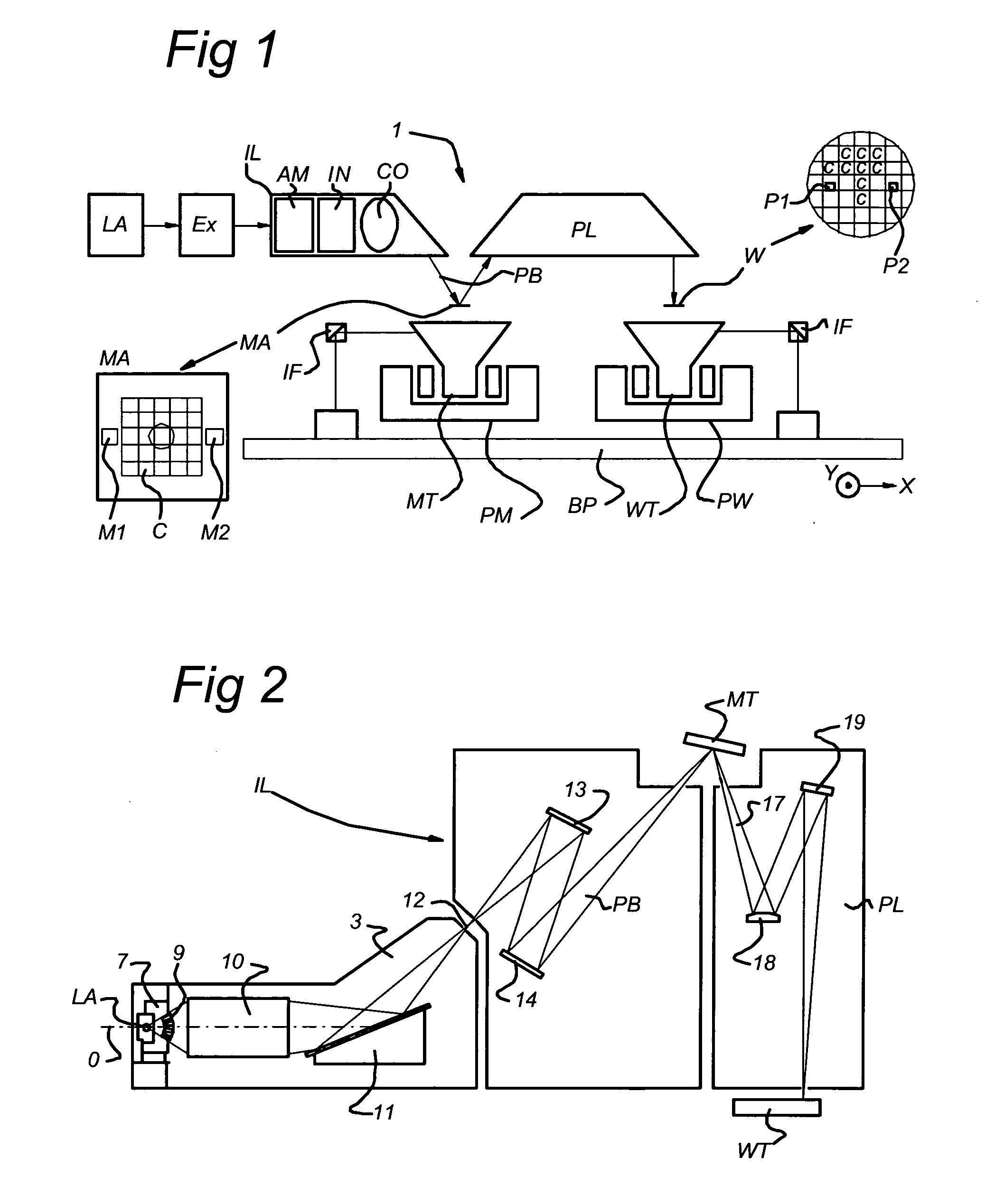
[0042]FIG. 1 schematically depicts a lithographic projection apparatus 1 according to a particular embodiment of the invention. The apparatus comprises a radiation system comprising a beam expander Ex, and an illumination system IL, for supplying a projection beam PB of radiation (e.g. EUV radiation). In this particular case, the radiation system also comprises a radiation source LA. A first object table (mask table) MT is provided with a mask holder for holding a mask MA (e.g. a reticle), and connected to a first positioning device PM for accurately positioning the mask with respect to item PL. A second object table (substrate table) WT is provided with a substrate holder for holding a substrate W (e.g. a resist coated silicon wafer), and connected to a second positioning device PW for accurately positioning the substrate with respect to item PL. The apparatus also includes a projection system (“lens”) PL (e.g. refractive, catadioptric or reflective system) for imaging an irradiate...

embodiment 2

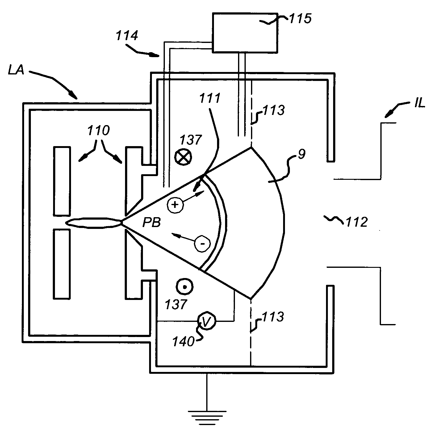
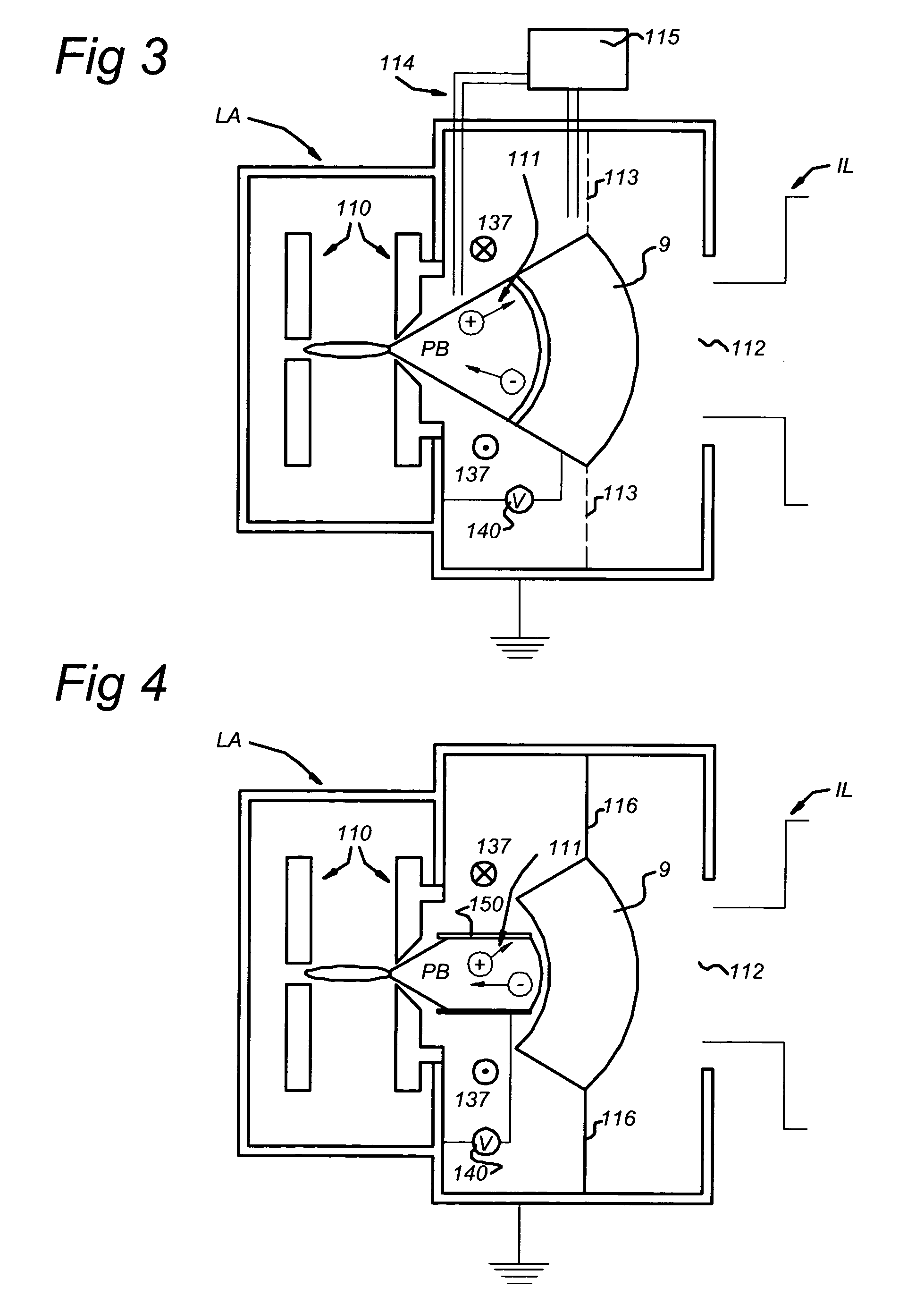
[0065]As mentioned above, in general, any type of electrode connected to the voltage source 140 may be provided to produce the desired electric field E between such an electrode and radiation source LA. An example is shown in a second embodiment, wherein the additional discharge between radiation source LA and contaminant barrier 9 is provided by separate electrode 150. Then, the electrode may be a cylinder 150, preferably used as a cathode, as shown in FIG. 4. The hollow cathode 150 is connected to a voltage source 140. This geometry is also beneficial in combination with a contaminant barrier 9, since the electric field, generated between hollow electrode 150 and radiation source LA can direct ionized electrode material, coming from radiation source LA, away from the projection beam PB, i.e. direct it towards platelets of the contaminant barrier 9. Since an additional electrode (150) is introduced, unlike the embodiment described in FIG. 3, it is no longer necessary that the conta...

embodiment 3

[0067]FIG. 5 depicts another embodiment, similar to the previous one, but without the contaminant barrier 9. This embodiment is based on the insight that the ionization energy of electrode materials of the radiation source LA, like molybdenum and tungsten, is much lower than the ionization energy of noble gases as argon, helium and xenon. Therefore, when molybdenum and tungsten atoms are present in a gas discharge, the ions will be efficiently ionized. It might even be possible to ionize all the sputtered electrode material of radiation source LA within the extra discharge, caused by the electric field E between radiation source LA and electrode 150, and to collect it electromagnetically on the electrode that acts as a getter. Thus, if total ionization of debris is possible, contaminant barrier 9 may not be necessary anymore.

[0068]Also this embodiment is not limited to the schematic drawing of this embodiment in FIG. 5. For example, this embodiment may also optionally comprise a mag...


PUM

PropertyMeasurementUnit
wavelengthaaaaaaaaaa

Abstract

A lithographic projection apparatus is disclosed. The apparatus includes a radiation system that includes a radiation source and an illumination system that supplies a beam of radiation, and a support structure that supports a patterning structure. The patterning structure is configured to pattern the beam of radiation according to a desired pattern. The apparatus also includes a substrate support that supports a substrate, a projection system that projects the patterned beam onto a target portion of the substrate, an electrode, and a voltage source that applies an electric field between the radiation source and the electrode to generate a discharge between the radiation source and the electrode.

Description

CROSS-REFERENCE TO RELATED APPLICATIONS[0001]This application is based on and claims the benefit of priority from European Patent Application No. 02080453.0 filed on Dec. 23, 2002, the contents of which are incorporated herein by reference.BACKGROUND OF THE INVENTION[0002]1. Field of Invention[0003]The present invention relates generally to the field of lithography. More specifically, the present invention relates to removal of debris from a lithographic apparatus.[0004]2. Description of Related Art[0005]In a lithographic apparatus, the size of features that can be imaged onto the substrate is limited by the wavelength of the projection radiation. To produce integrated circuits with a higher density of devices, and, hence, higher operating speeds, it is desirable to be able to image smaller features. While most current lithographic projection apparatus employ ultraviolet light generated by mercury lamps or excimer lasers, it has been proposed to use shorter wavelength radiation, e.g...

Claims


Application Information

Patent Timeline
Patent Type & Authority Patents(United States)
IPC IPC(8): G03B27/52G03B27/42G03B27/72G21K5/00G03F7/20G21K5/02H01L21/027H05H1/24
CPCG03F7/70941G03F7/70916H01L21/027
Inventor BAKKER, LEVINUS PIETER
Owner ASML NETHERLANDS BV
Why Eureka
Try Eureka