Interferometric methods result in accuracies of less than one
micrometer over ranges of up to several millimeters.
Triangulation techniques result in devices with accuracy in the
micrometer range, but can only measure distances out to several inches.
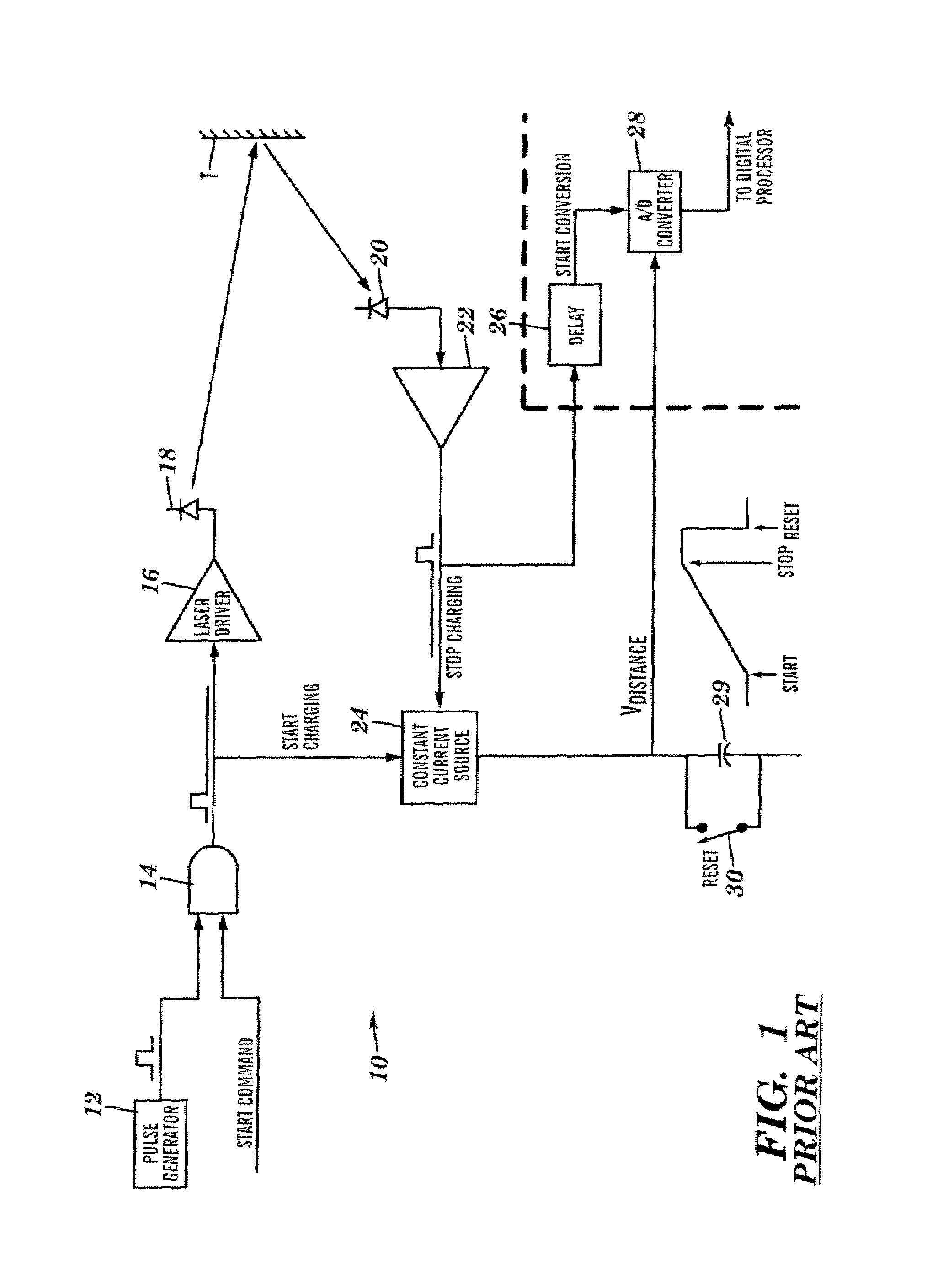
However, this counter approach has quantization errors, which is remedied by random dithering or interpolation methods.
All of these pulsed TOF methods are conceptually simple, although their implementation is usually complex and expensive.
Such
broadband electronic components are expensive, and drive up the overall cost of the
system.
It is also difficult for pulse-TOF systems to measure velocity.
Both methods suffer from accuracy problems, and are relatively expensive to implement because they require the use of
broadband electronics to ensure the fidelity of the pulses.
This is one of the major drawbacks of phase measuring methods.
Another drawback is that since the modulation occurs in a continuous-wave fashion, the average power of the carrier must be high in order to be able to obtain a significant received signal for
large target distances.
Yet another drawback concerns undesirable phase
delay changes of the electronic circuitry with changes in ambient environmental conditions, especially temperature.
Also,
gain changes in AGC (Automatic-
gain-control) circuitry will cause changes in phase as well, and these changes cannot be reliably calibrated and subtracted out with commonly used on-board reference methods.
This arises primarily from non-linearities within the mixers and amplifiers, and from drift in
gain and electronic
signal delay times due to changes in ambient environmental conditions.
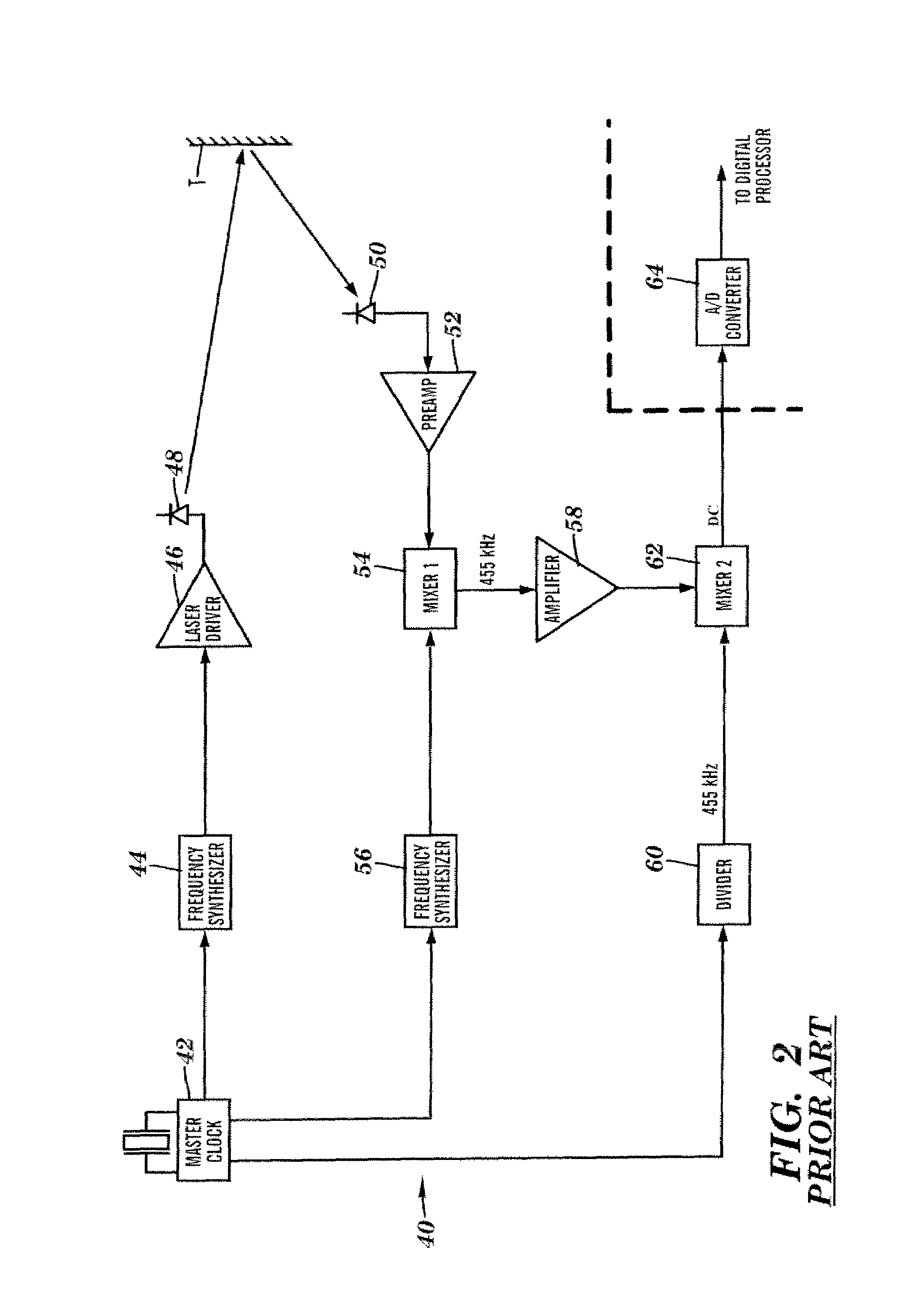
Furthermore, since the DC signal is proportional to the cosine of the
phase difference, there will be certain phase differences that result in imprecise phase
estimation owing to the
slow rate of change of the cosine function, most noticeably at nπ phase differences, where n is an integer.
In other words, whenever the distance to the target is approximately 802.5n millimeters, the precision of the
distance measurement is questionable.
There is yet another problem with the signal output from the mixer.
If one of the signals amplitude unexpectedly changes due to
noise or fluctuations in the return signal, then the interpretation of the mixer's output can lead to serious distance estimate inaccuracies.
The homodyne phase measuring rangefinder has the same drawbacks of the heterodyning rangefinder, especially as related to nonlinearities within the electronic functions, particularly the
phase splitter and the mixers, as well as the imprecision at distances proportional to nπ
phase difference, and gain and
delay drifts with changes in environmental conditions.
Both the homodyne and
heterodyne methods suffer from the aforementioned range
ambiguity problem, which can be remedied by utilizing a second, lower,
operating frequency whose first
ambiguity is beyond the operating range of the device.
Lastly, since the
laser is amplitude modulated for a relatively long period of time, and since the average
laser output power must be limited to 1 mW for eye-safety considerations, the maximum range for
visible laser emissions is therefore limited as well.
While the coherent burst method seems to intrinsically solve many of the problems of eye-safe
distance measurement, some problems still remain.
Any errors in these differences will cause an uncalibratable
distance error.
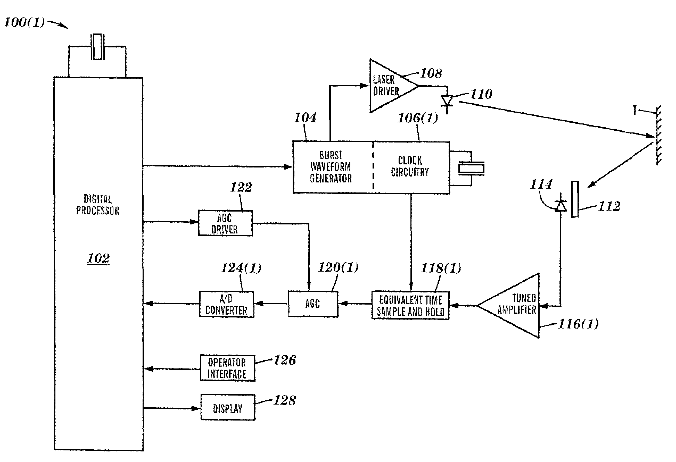
Thirdly, the output of the mixers are still a function of the amplitude of the input signals, and, lastly, uncalibrated phase delays are introduced when Automatic-gain-control methods are employed.
In sum, these errors make it very difficult to economically achieve accuracy better than 0.1″ in a compact or hand-held distance measuring unit.
For phase measurement
ranging, AGC is particularly problematic because when the gain of an electronic amplification circuit is changed, an
RC time constant or
semiconductor junction
delay time within that circuit is also usually changed, meaning the delay of the signal through that circuit is also changed.
Further, since it is unknown what the correct AGC gain should be a priori it is extremely difficult to accurately calibrate this AGC-induced variable delay and subtract it from the distance measurement.
This is a subtle yet important defect in the prior art.
But these methods just move the
phase error problem from the receive signal path to the
transmitter signal path.
When the power levels of the emissive devices are changed, their operating characteristics change, and they will generally introduce several picoseconds of
signal delay change.
Furthermore, these errors will not be calibrated because the calibration will occur at one level of emission, and the actual distance measurement operation will occur at a different level having a different phase delay.
Also, if the transmitted signal is attenuated too much, the emission will not be visible on the target and pointing accuracy will suffer.
But this has the obvious
disadvantage of increased cost and size, and reduced reliability.
However, this approach also tends to be complex and costly.
This method also suffers from increased complexity and cost.
But doubling the number of receive paths obviously comes with increased cost and complexity, and reduced reliability.
Most of these methods also suffer from serious electronic
signal delay calibration problems.
This method does successfully implement an optical AGC function, but suffers from the common problems of increased cost and complexity.
Lastly, partial blocking of the collection lens can work as an optical AGC, but it too has increased complexity, reduced reliability, and should not be relied upon in and of itself because of its limited
dynamic range.

