Optical film and liquid crystal display using the same

a liquid crystal display and optical film technology, applied in the direction of instruments, polarising elements, other domestic articles, etc., can solve the problems of reducing the viewing angle, difficult to produce acceptable color images in tn, and largely unsolved viewing angle problems, so as to improve the viewing angle without increasing the thickness, minimize problems, and improve the effect of viewing angl

Inactive Publication Date: 2007-04-24
KONICA CORP
View PDF4 Cites 23 Cited by
  • Summary
  • Abstract
  • Description
  • Claims
  • Application Information

AI Technical Summary

Benefits of technology

[0017]An object of the present invention is to provide a film for a liquid crystal display which enables enhancement of viewing angle without increasing the thickness, and provide a polarizing plate as well as a liquid crystal display using the same. Another object of the present invention is to provide a film for a liquid crystal display which minimizes problems due to abnormal light emission, while exhibiting excellent tearing strength as well as excellent water resistance, and a polarizing plate as well as a liquid crystal display using the same. Still another object of the present invention is to provide a film for a liquid crystal display which is less expensive and thinner, while exhibiting high performance optical anisotropy, and a polarizing plate as well as a liquid crystal display using the same.

Problems solved by technology

As a result, the following problems which are tinted blue or yellow have occurred.
Viewing angle decreases, and it is difficult to produce acceptable color images in TN.
However, the viewing angle problem is largely unsolved.
Further, when cellulose ester film is produced by dissolving cellulose ester and casting the resulting solution, any portion which has been subjected to insufficient esterification tends to remain in the film as insoluble foreign matter particles.
When the resulting film is employed to produce liquid crystal display elements, it has been found that the insoluble foreign matter particles cause problems such as hindering the formation of a polarizing state and forming abnormal light emission due to its difference in the refractive index from cellulose ester.
Further, under normal light condition, it was difficult to detect said abnormality due to the presence of insoluble particles.
In recent years, the high precision of liquid crystal displays is progressing and problems due to such foreign matter particles have increasingly been noted.

Method used


Image

  • Optical film and liquid crystal display using the same
  • Optical film and liquid crystal display using the same
  • Optical film and liquid crystal display using the same

Examples


example 1

(Preparation and Evaluation of Fatty Acid Cellulose Ester Film)

[0160]The compositions described below were placed in a tightly sealed pressure vessel, heated to 80° C., and completely dissolved while stirring under a pressure of 500 kPa, while maintaining said temperature.

[0161]

Cellulose acetate propionate (CAP)120weight parts(substitution degree is described in Table 1)2-(2′-hydroxy-3′,5′-di-t-butylphenyl)1weight part(UV absorber)Ethyl phthalyl ethyl glycolate (plasticizer)4weight partsFine silica particles (AEROSIL 2000.1weight partmanufactured by Nihon Aerosil Co., Ltd.)(0.016 μm)Methyl acetate300weight partsEthanol45weight parts

[0162]The resulting dope was cooled to 40° C., while the pressure was reduced to normal pressure. The dope set aside overnight, and was then subjected to a deforming process. Thereafter, the resulting solution was filtered, employing Azumi filter paper No. 244, manufactured by Azumi Roshi Co., Ltd. The resulting dope was cooled and maintained at 35° C., a...

example 2

(Preparation and Evaluation of Liquid Crystal Display)

[0178]Film No. 1 of Example 1 was treated with an aqueous 2.5 mol / liter sodium hydroxide solution at 40° C. for 60 seconds and subsequently washed with water for 3 minutes. Thus an alkali-treated film, in which a saponified layer was formed, was obtained.

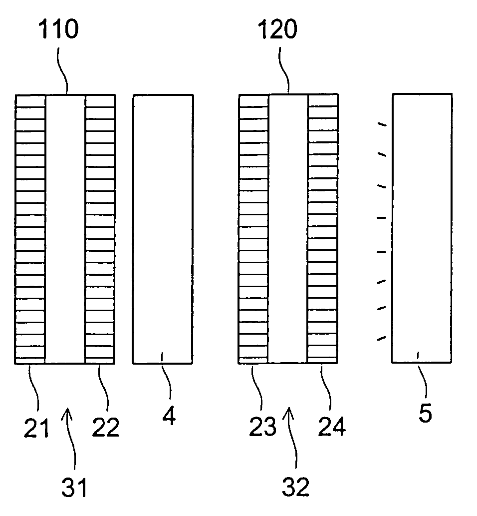
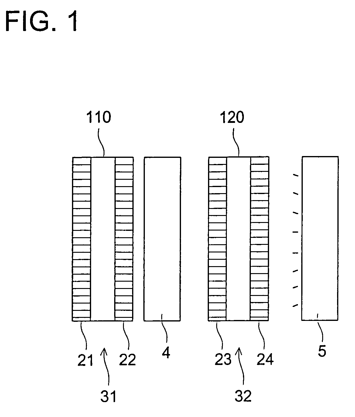
[0179]Subsequently, a 120 μm thick polyvinyl alcohol film was immersed in 100 weight parts of an aqueous solution containing one weight part of iodine and 4 weight parts of boric acid, and then stretched to 4 times original length at 50° C. by a factor of 4 at 50° C. Thus a polarizing film was prepared. A polarizing plate was prepared by adhering said alkali-treated film onto both surfaces of the resulting polarizing film, employing a 5 percent aqueous totally saponified type polyvinyl alcohol solution as the adhesive. No. 1 Liquid Crystal Display was obtained by providing the resulting polarizing plate on both surfaces of a VA type liquid crystal cell.

[0180]Liquid Crystal Displa...

example 3

(Evaluation of Fatty Acid Cellulose Ester Film)

[0185]Films No. 1, 5, and 6 were subjected to measurement and evaluation employing the methods described below. Table 4 shows the results.

(Transmittance)

[0186]Transmittance of light having a wavelength of 550 nm was measured employing a spectrophotometer (U-3400 manufactured by Hitachi Seisakusho).

(Moisture and Heat Resistance)

[0187]Two film sheets were prepared by blanking a film. A polyurethane adhesive was applied to one surface of the resulting film sheet. Then a polarizing film was prepared by adhering the resulting sheet onto both surfaces of a polarizing element (30 nm) comprised of polyvinyl alcohol and dichroic dyes. The thus obtained polarizing film was cut into 100×100 mm squares, and was adhered onto a glass plate, employing a acryl based adhesive, and stored at 80° C. and 90 percent relative humidity for 1,000 hours. Thereafter, the peeling state of said film was observed and the degree of coloration or chromaticity (“b” va...


PUM

PropertyMeasurementUnit
thicknessaaaaaaaaaa
thicknessaaaaaaaaaa
thicknessaaaaaaaaaa

Abstract

A film for a liquid crystal display comprising a fatty acid cellulose ester film having an acetyl group and a propionyl group is disclosed. Sum of degree of acetyl substitution (DSac) and degree of propionyl substitution (DSpr) of the fatty acid cellulose ester film of the film is 2.8 or less, and a retardation value (Rt value) in the thickness direction define by Formula 1 is 60 to 300 nm.

Description

CROSS REFERENCE TO RELATED APPLICATION[0001]This Application is a Divisional of U.S. patent application Ser. No. 10 / 623,087, filed Jul. 18, 2003, now U.S. Pat. No. 6,740,370, which, in turn, was a Divisional of U.S. patent application Ser. No. 10 / 288,689, filed Nov. 5, 2002, now U.S. Pat. No. 6,623,811, which, in turn, was a Divisional of U.S. patent application Ser. No. 09 / 691,310 filed Oct. 18, 2000, now U.S. Pat. No. 6,503,581.FIELD OF THE INVENTION[0002]The invention relates to such a film employed in a liquid crystal display as a protective film, view angle enlarging film, an optically anisotropic film such as a phase difference film, a polarizing plate employing film, and a liquid crystal display.[0003]A liquid crystal display operates at low voltage as well as low power consumption, and further, can be directly connected to an IC circuit. Specifically, it is possible to decrease its thickness. As a result, it is widely employed in word processors, personal computers, and the ...

Claims


Application Information

Patent Timeline
Patent Type & Authority Patents(United States)
IPC IPC(8): G02F1/1335G02B1/04C08B3/16C08L1/14G02B5/30G02F1/13363
CPCB32B27/08C08L1/14C09K19/2007C09K19/2014C09K19/32G02B5/3033G02F1/133634C08B3/16Y10T428/28C09K2019/0429C09K2219/03Y10T428/1041Y10T428/1036Y10T428/105Y10T428/1005Y10T428/10Y10T428/1077Y10T428/31786C09K2323/035C09K2323/057C09K2323/02C09K2323/031C09K2323/03C09K2323/00
Inventor SHIBUE, TOSHIAKIHONDA, MAKOTOKUBO, NOBUOKUZUHARA, NORIYASUUMEDA, HIROKIKAWAKAMI, SOTAYAJIMA, TAKATOSHI
Owner KONICA CORP
Why Eureka
Try Eureka