Magnetically enhanced, inductively coupled plasma source for a focused ion beam system

a plasma source and focused ion beam technology, applied in the direction of optical radiation measurement, particle separator tube details, instruments, etc., can solve the problems of reducing the efficiency of laser beams, and reducing the processing time in production applications and laboratories, so as to eliminate the effect of plasma potential modulation and high ion density

Active Publication Date: 2007-07-10
FEI CO
View PDF1 Cites 154 Cited by
  • Summary
  • Abstract
  • Description
  • Claims
  • Application Information

AI Technical Summary

Benefits of technology

[0012]The present invention provides a method for forming a plasma that is suitable as a high brightness ion source. The plasma is inductively coupled to a compensated RF antenna and can be used in conjunction with focusing optics to produce a focused ion beam for milling and deposition. According to an aspect of the present invention, the RF antenna can be implemented as a helical coil that surrounds a plasma tube. An RF current source is applied to the antenna to induce ionization of the plasma gas in the tube. An impedance matching circuit is provided to allow efficient power transfer to the plasma with appropriate phase shift across the antenna to eliminate plasma potential modulation. The ionized plasma is extracted into an ion beam and focused by ion optics. The ion beam so formed is substantially free of undesirable energy oscillations arising from the RF antenna. Because the RF source imparts only small or ideally no oscillations to the plasma potential, the consequent axial energy spread of the beam arising there from is small. Hence, the ionizing source does not cause substantial chromatic aberration. Moreover, the RF source imparts to the plasma a high ion density. When coupled with focusing mechanisms, the high-density beam is highly suitable for milling and deposition.

Problems solved by technology

Although use of liquid metal ion sources has increased, their application is often limited due to metal ion contamination and relatively low obtainable beam currents.
Lower beam currents result in lower erosion rates and hence longer processing times in production applications and in laboratories.
A challenge exists in generating high current, low energy beams for implantation from an RF plasma source.
A complication associated with using an RF driven ion source for low energy ion implantation is the undesirable oscillations imparted to the plasma potential, through capacitive coupling from the antenna to the plasma.
Such a highly modulated beam is unsuitable for low energy ion implantation, due to the broadened projected ion range into the target.
Ion energy modulation is even less suitable for FIB systems, due to the associated chromatic aberrations generated in the beam.
Clearly, the modulations imparted by the RF source substantially and undesirably impact the focus of the beam.
At least partially for this reason, it is believed that RF sources have not been successfully used with FIB systems.

Method used


Image

  • Magnetically enhanced, inductively coupled plasma source for a focused ion beam system
  • Magnetically enhanced, inductively coupled plasma source for a focused ion beam system
  • Magnetically enhanced, inductively coupled plasma source for a focused ion beam system

Examples


Embodiment Construction

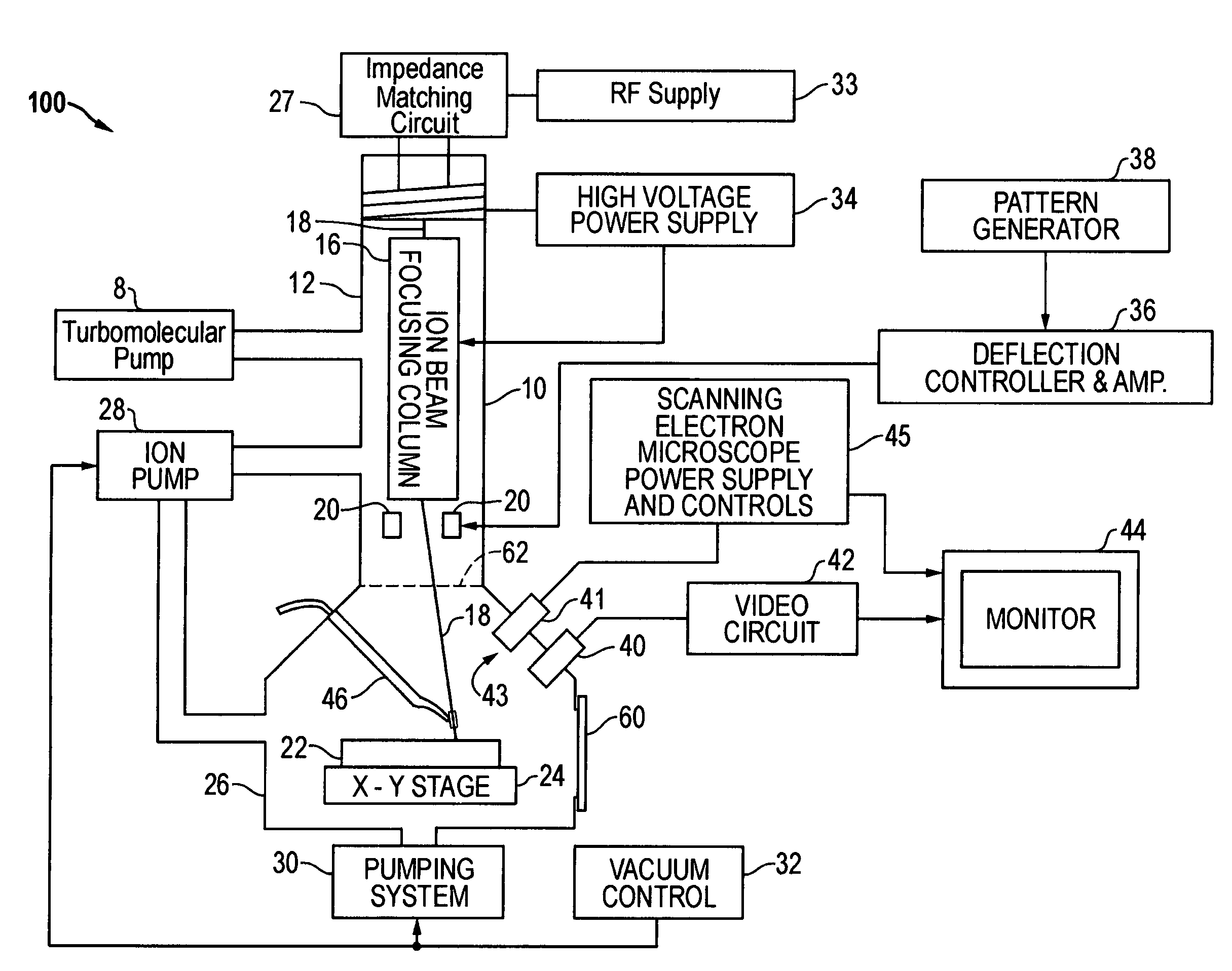
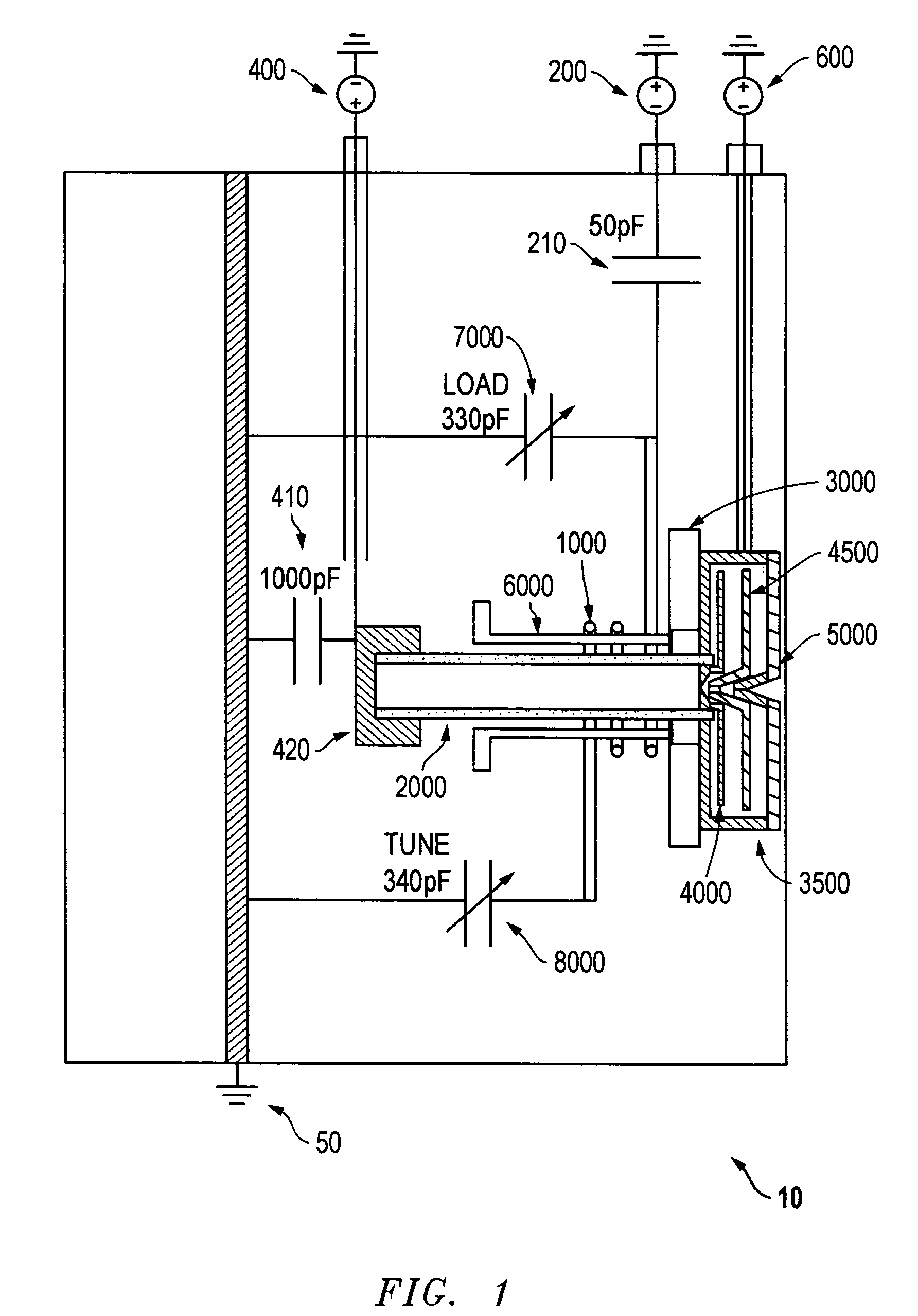
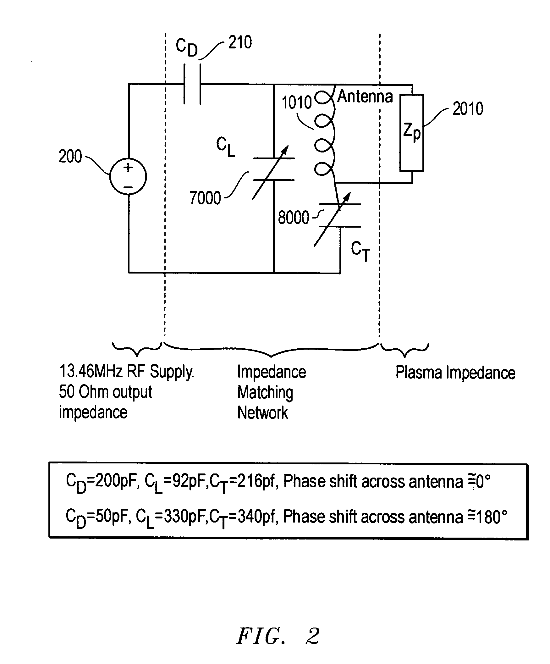
[0020]FIG. 1 shows a diagram of an embodiment of an ion plasma source 10 according to the method of the present invention. A coil 1000 is capacitively coupled by impedance 210 to an RF source 200. Note that the capacitances shown in FIG. 1 are nominal values that readily can be selected by one of skill in the art according to the frequency of operation of the coil, as will be described further below. Coil 1000 is preferably a multi-turn coil that wraps around a dielectric plasma tube 2000 so that the axis of the coil substantially coincides with the axis of chamber 2000 and the beam axis.

[0021]When driven by source 200, coil 1000 forms a helical RF antenna. Driving the coil with an RF source can impart a time-varying potential to the plasma, due to capacitive coupling. That is, the coil can produce a radial electric field that modulates the plasma. This is undesirable because it creates a spread in the beam energy, resulting in chromatic aberration. However, in a preferred embodimen...


PUM

PropertyMeasurementUnit
energyaaaaaaaaaa
energy spreadaaaaaaaaaa

Abstract

The present invention provides an inductively coupled, magnetically enhanced ion beam source, suitable to be used in conjunction with probe-forming optics to produce an ion beam without kinetic energy oscillations induced by the source.

Description

[0001]This application claims priority of U.S. Provisional Application No. 60 / 546,142, filed on 20 Feb. 2004.TECHNICAL FIELD OF THE INVENTION[0002]The present invention relates to the field of focused ion beam systems.BACKGROUND OF THE INVENTION[0003]Focused ion beam (FIB) systems are widely used in characterization or treatment of materials on microscopic to nanoscopic scales. For example, focused ion beam systems are used in manufacturing operations because of their ability to image, mill, deposit and analyze with great precision. Ion columns in FIB systems using gallium liquid metal ion sources (LMIS), for example, can provide five to seven nanometers of lateral resolution. Such focused ion beam systems are commercially available, for example, from FEI Company, Hillsboro, Oreg., the assignee of the present application. Although use of liquid metal ion sources has increased, their application is often limited due to metal ion contamination and relatively low obtainable beam curren...

Claims


Application Information

Patent Timeline
Patent Type & Authority Patents(United States)
IPC IPC(8): H01J49/10H01J27/02C23C16/00H01J37/08
CPCH01J27/16H01J37/321H01J37/08H01J2237/0815H01J37/32183H01J37/241H01J37/3211H01J37/32669
Inventor KELLER, JOHNSMITH, NOELBOSWELL, RODERICKSCIPIONI, LAWRENCECHARLES, CHRISTINESUTHERLAND, ORSON
Owner FEI CO
Why Eureka
Try Eureka