
Spectroscopic apparatus using spectrum narrowed and stabilized laser with Bragg grating

a raman spectroscopic and stabilized laser technology, applied in the direction of spectrometry/spectrophotometry/monochromators, optical radiation measurement, instruments, etc., can solve the problems of inability to align optics, the relatively short excitation laser wavelength often gave rise to intense and interfering fluorescence, etc., to improve the overall stability of the device

Active Publication Date: 2007-07-17
METROHM SPECTRO INC
View PDF11 Cites 40 Cited by
  • Summary
  • Abstract
  • Description
  • Claims
  • Application Information

AI Technical Summary

Benefits of technology

"The present invention provides a low cost Raman spectrometer that is portable and can be used in various environments. The spectrometer includes a laser, a wavelength dispersion element, and a photo detector. The laser generates the excitation for the sample, and the dispersed spectrum is collected and filtered to remove unwanted signals. The filtered spectrum is then detected using the photo detector. A computer processes the data collected from the spectrometer to analyze the sample. The invention also includes a novel spectrum narrowed and stabilized diode laser that improves the stability of the device. Additionally, the invention provides a multi-wavelength laser source with wavelength modulation capability for fluorescence suppression in Raman spectroscopy."

Problems solved by technology

However, the large physical size of these lasers, the difficulty in aligning optics, and the overall fragility of the systems limited Raman spectroscopy to be used as a laboratory analyzing method.
Besides, the relatively short excitation laser wavelength often gave rise to intense and interfering fluorescence which obscured the weak Raman scattering.
In recent years, even with the arrival of the diode laser as the popular choice of Raman excitation source, the laser remains very expensive and delicate.
As a result, Raman instruments are still not well suited for field uses, such as in industrial manufacturing or processing facilities.
The lack of a low cost, rugged, and stable diode laser remains a major barrier to develop a low cost and portable Raman instrument which can generate quality high resolution Raman spectrum.
The main issues for diode lasers in Raman spectroscopic application are their spectral stability and spectral linewidth.
The inherent instability stems from a broad gain curve which allows multiple longitudinal modes and transverse modes to co-exist within the gain curve and with spatial distribution over the whole emitter width.
The standard Fabry-Perot design does not allow for any discrimination between the modes, and consequently, many different lasing modes will be present at a given time.
Furthermore, these modes are constantly competing and inducing mode-hopping, which in turn affects the laser emission wavelength and spectral intensity distribution.
However, due to the mode instability and relatively broad spectrum of a regular F-P diode laser, LRRS has only very limited utilities due to poor quality Raman spectrum generated.
These are monolithically integrated devices with embedded grating structure in gain region in case of the DFB diode laser and outside of gain region in case of the DBR diode laser.
However, these devices are typically difficult to manufacture and require high precision multi-epitaxial growth, therefore leading to high cost.
Due also to the single spatial mode structure, the power level of these lasers is typically limited to be less than 200 mW in near infrared region.
In addition, optical feedback can further introduce power instability and mode-hopping due to weak cavity and short cavity length (low cavity Q value).
However, due to complexity, high cost and low yield of the product, this product is not currently commercially available.
The system is quite complicated, and optical alignment is very delicate and difficult.
However, this type of ECL is quite delicate and vulnerable.
Any slight change in the cavity mechanically or thermally can cause instability in emission wavelength.

Method used


Image

  • Spectroscopic apparatus using spectrum narrowed and stabilized laser with Bragg grating
  • Spectroscopic apparatus using spectrum narrowed and stabilized laser with Bragg grating
  • Spectroscopic apparatus using spectrum narrowed and stabilized laser with Bragg grating

Examples


Embodiment Construction

[0040]Preferred embodiments of the invention will now be set forth in detail with reference to the drawings.

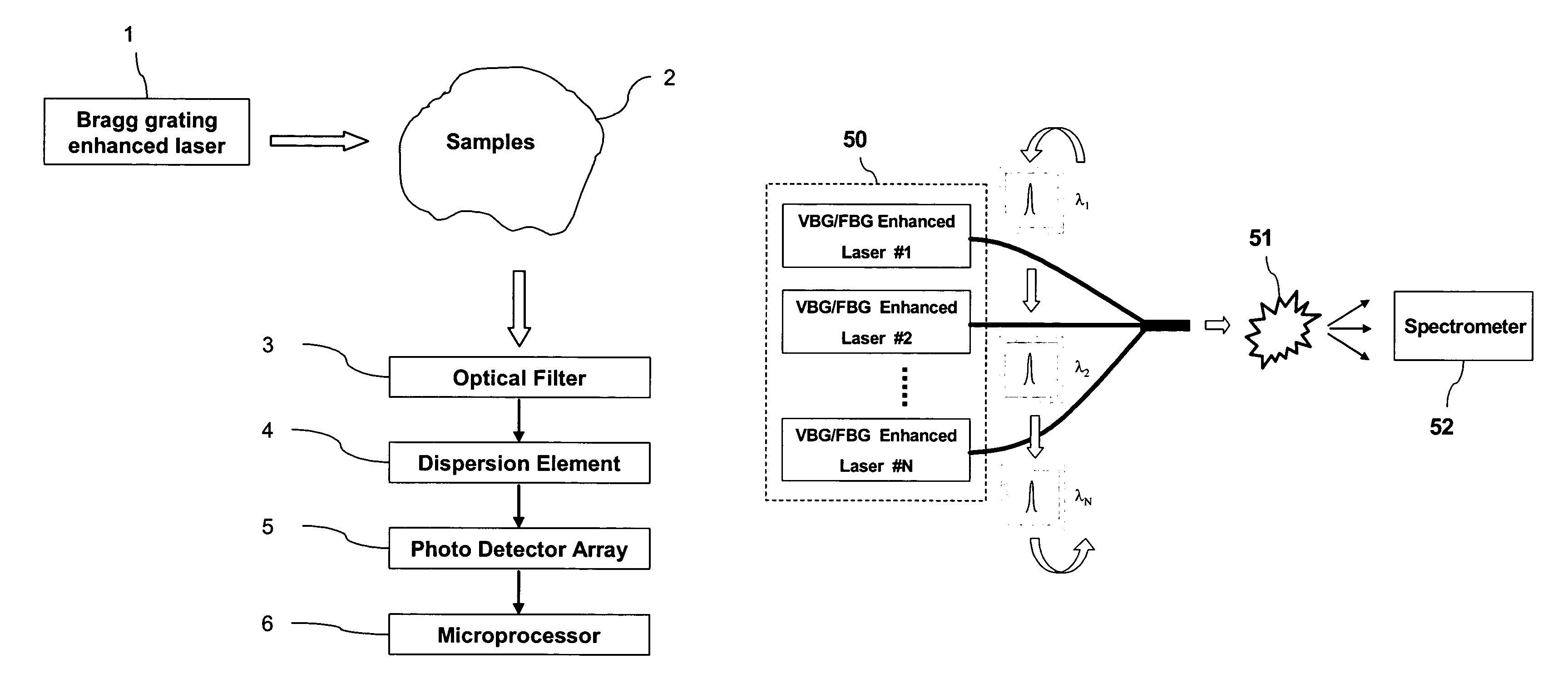
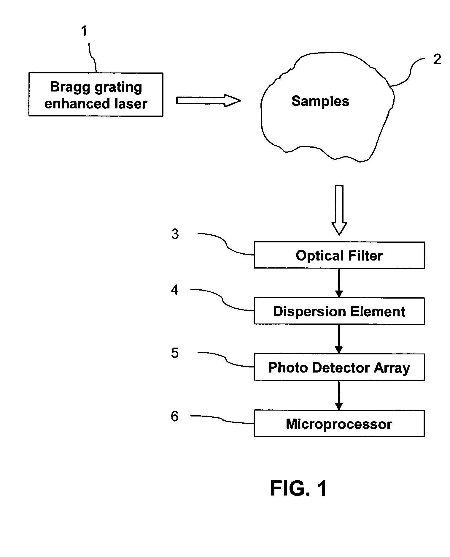
[0041]An example of the disclosed Raman spectrometer is illustrated in FIG. 1. The apparatus includes a Bragg grating enhanced laser element 1, an optical filter element 3, a wavelength dispersion element 4, as well as an array or single element photo detector 5, plus a control and data processing unit such as a computer or microprocessor 6. This apparatus is used to measure the properties of the samples 2 by means of Raman spectroscopy. The laser 1 is used as an excitation source for generating Raman scattering off the sample 2 being analyzed. The Raman spectrum is then collected and filtered to remove the Rayleigh scattering. The obtained spectrum containing Raman signal is dispersed using the wavelength dispersion element 4 such as a grating or prism that can be either stationary or scanning. The dispersed Raman spectrum is then detected using an array photo detector or a s...


PUM

PropertyMeasurementUnit
power levelaaaaaaaaaa
reflectivityaaaaaaaaaa
sizeaaaaaaaaaa

Abstract

An apparatus for measuring properties of physical matters by means of Raman spectroscopy including a laser element, a wavelength dispersion element, an array or single element detector, and a control and data processing unit. The laser element, which is used to excite Raman scattering, is spectrum narrowed and stabilized by attachment of a Bragg grating device. The grating can be either a volume Bragg grating (VBG) written inside a glass substrate or a fiber Bragg grating (FBG) written inside an optical fiber. A laser element can be provided with a wavelength modulation capability for fluorescence background suppression.

Description

REFERENCE TO RELATED APPLICATION[0001]The present application claims the benefit of U.S. Provisional Application No. 60 / 519,268, filed Nov. 13, 2003, whose disclosure is hereby incorporated by reference in its entirety into the present disclosure.FIELD OF THE INVENTION[0002]This invention generally relates to apparatus for analyzing substances by optical spectroscopy and, more specifically to Raman Spectroscopic apparatus using a spectrum narrowed and stabilized laser with Bragg gratings.DESCRIPTION OF RELATED ART[0003]Raman spectroscopy has become an effective analytical technique for chemical analysis. When a beam of monochromatic light is incident on a sample, some of the light is scattered by the material. Most of the scattered light does not exhibit a change in wavelength. This is called Rayleigh scattering. A tiny portion of the scattered light is shifted in wavelength by the molecular vibration and rotation of the molecules in the sample. This type of scattering is called Ram...

Claims


Application Information

Patent Timeline
Patent Type & Authority Patents(United States)
IPC IPC(8): G01J3/44G01J3/10G01J3/433G01N21/65
CPCG01J3/02G01J3/0205G01J3/0208G01J3/0218G01J3/0227G01J3/10G01J3/1895G01J3/433G01J3/44G01N21/65G02F2001/3542H01S3/109H01S5/0092H01S5/141H01S5/146H01S5/147H01S5/4012G02F1/3542H01S5/2036
Inventor WANG, SEAN XIAOLUZHOU, XIN JACK
Owner METROHM SPECTRO INC
Learn More