Laser curing apparatus with real-time monitoring and control

a curing apparatus and real-time monitoring technology, applied in the field of curing equipment, can solve the problems of high cost and high cost of curing system, and achieve the effect of improving curing results and avoiding overcuring

Inactive Publication Date: 2007-07-17
METROHM SPECTRO INC
View PDF13 Cites 26 Cited by
  • Summary
  • Abstract
  • Description
  • Claims
  • Application Information

AI Technical Summary

Benefits of technology

[0008]To achieve the above and other objects, the present invention is directed to a laser based curing apparatus with a Raman spectroscopic sensor for real-time, non-invasive cure monitoring and control. Unlike previous approaches, the curing laser itself is used as the Raman excitation light source in the current invention. Since no additional laser is required, the cost of the monitoring system is greatly reduced. The power requirement for the curing laser is generally in several mW to hundreds of mW range depending on the material and the size of the curing area. This power is strong enough to generate significant Raman emission. In addition, as the wavelength of the curing laser is generally selected to match with the absorption band of the material, the resonant Raman effect may be employed in which, the Raman emission can be enhanced by 1000–10000 times. All these greatly reduce the requirement for the sensitivity of the spectrometer, making it possible to use a low-cost spectrometer for cure status monitoring.
[0009]It is thus one goal of the current invention to provide a laser based light source for high precision curing of a material. The laser can be a semiconductor laser diode (LD), a diode pumped solid-state laser (DPSSL), or other kinds of lasers. Depending on the material to be cured, the emission wavelength of the laser can be either in ultraviolet / visible (UVVIS) range for photochemical curing or in near infrared / infrared (NIR / IR) range for thermal curing. The laser has a narrow linewidth that can perfectly match with the absorption peak of the material, which results in a better curing efficiency than that of conventional lamps. The intrinsic beam size of the laser is small, which is ideal for applications that require accurate spot curing. The beam size of the laser can also be expanded using a secondary optical system to adapt for other applications. Depending on the requirement for different materials, the laser can work either in continuous wave (CW) mode or in pulsed mode by direct or external modulation technique. The pulse width and repetition rate of the laser can be controlled to match with the thermal relaxation cycle of the material as to achieve the best curing result in bond strength, surface hardness, material shrinkage, curing speed and heat generation.
[0011]It is yet another goal of the current invention to utilize the obtained Raman signal to control the curing profile of the laser, which includes laser power, intensity, pulse width, duty cycle, and / or repetition rate variation with time, in order to further improve the curing result. Based on previous research results, many materials cure best under varied light exposure during the cure process. Once the spectroscopic sensor indicates that the curing reaches its optimum condition, the laser can be automatically turned off by the feedback control system to avoid over-curing.

Problems solved by technology

The difficulty of using Raman spectroscopy for cure monitoring lies in its high cost.
Both of them are very expensive for a curing system.

Method used


Image

  • Laser curing apparatus with real-time monitoring and control
  • Laser curing apparatus with real-time monitoring and control
  • Laser curing apparatus with real-time monitoring and control

Examples


Embodiment Construction

[0020]Preferred embodiments of the present invention will now be set forth in detail with reference to the drawings.

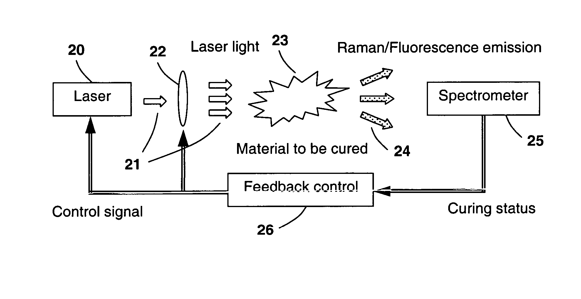
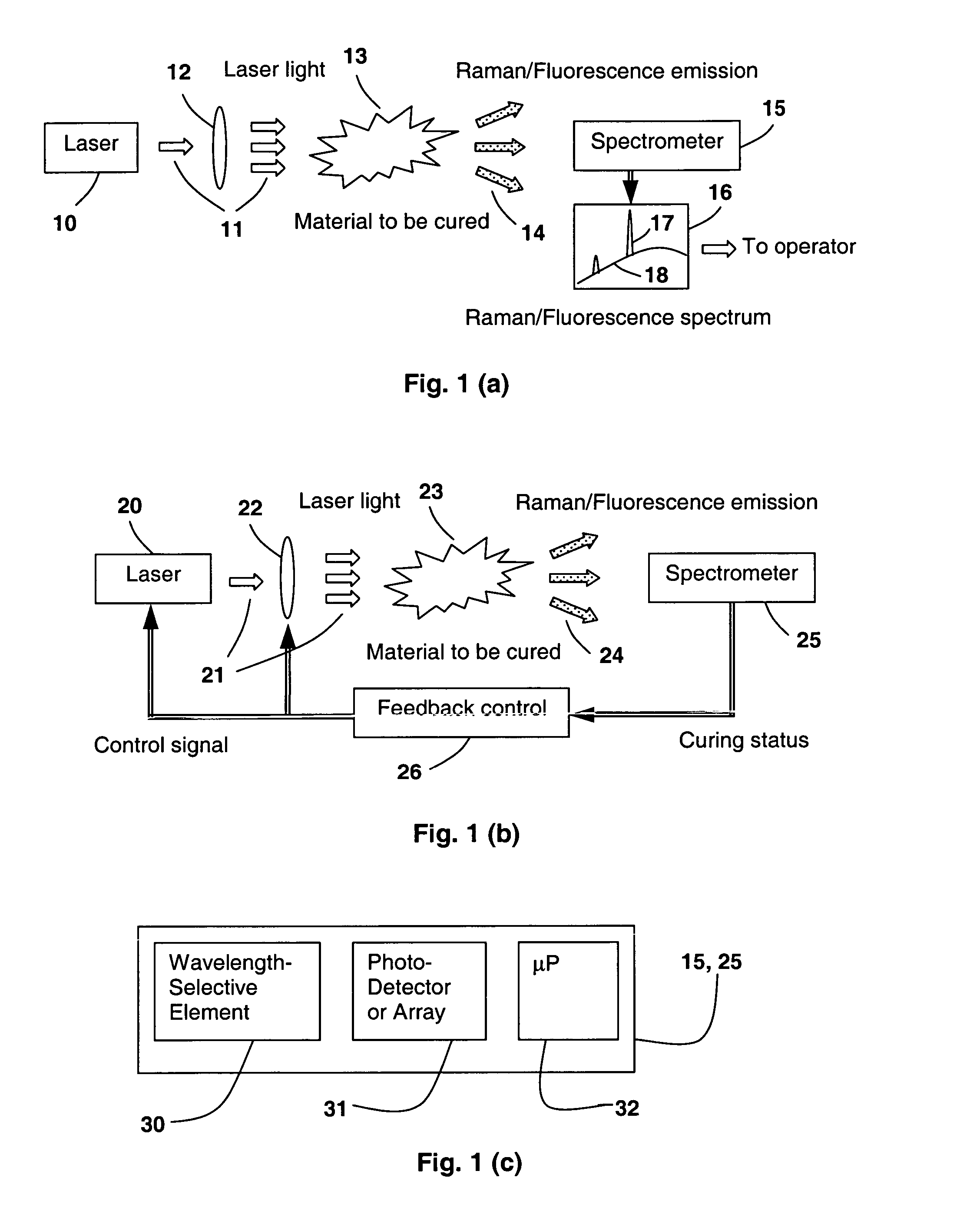
[0021]A schematic representation of the laser curing apparatus is shown in FIGS. 1(a) and (b). In FIG. 1(a), the curing laser 10 produces laser light 11, which is first transformed (focused, expanded, collimated) by a secondary optical system 12 and then absorbed by the material 13 to induce and / or accelerate the polymerization process. The laser light 11 in the mean time excites Raman / fluorescence emission 14 from the material 13 during the cure process. An optical spectrometer 15 is used to collect and analyze the Raman / fluorescence signal and produces a Raman / fluorescence spectrum 16, which is composed of Raman signal 17 and fluorescence background 18. The intensity and wavelength position of the Raman signal 17 are used to determine the curing status of the material in real time since the Raman signal 17 is directly related to the vibration / rotational energy levels...


PUM

PropertyMeasurementUnit
output poweraaaaaaaaaa
sizeaaaaaaaaaa

Abstract

In a laser based curing apparatus, the acts both as the curing light and the excitation source for a Raman spectroscopic sensor. The spectroscopic sensor provides real-time, in situ, non-invasive curing status monitoring via Raman spectroscopy. The spectroscopic information can be further used to control the operation parameters of the laser to achieve the optimum cure result.

Description

REFERENCE TO RELATED APPLICATION[0001]The present application claims the benefit of U.S. Provisional Application No. 60 / 604,711, filed Aug. 27, 2004, whose disclosure is hereby incorporated by reference in its entirety into the present disclosure.FIELD OF THE INVENTION[0002]This invention generally relates to a curing apparatus, and more specifically to a laser based curing apparatus with real-time monitoring and control by means of Raman spectroscopy.DESCRIPTION OF RELATED ART[0003]The rapid development of solid state lasers makes it possible to replace the conventional lamp based curing light source with a compact, highly efficient, low power-consumption laser based curing light source. The laser based curing light source is suitable for many applications including but not limited to high precision assembly, dental resin curing, and micro-biomedical devices. Such applications require accurate and fast curing with optimum curing condition, such as low shrinkage, high strength, low ...

Claims


Application Information

Patent Timeline
Patent Type & Authority Patents(United States)
IPC IPC(8): G01N21/65G01N21/64
CPCA61C1/0046G01J3/44G01N21/6402G01N21/65G01J3/10A61C19/003
Inventor WANG, SEAN XIAOLULI, QUNLI, QINGXIONG
Owner METROHM SPECTRO INC
Why Eureka
Try Eureka