Method and apparatus for providing power to a microprocessor with integrated thermal and EMI management

Inactive Publication Date: 2007-07-17
MOLEX INC
View PDF77 Cites 30 Cited by
  • Summary
  • Abstract
  • Description
  • Claims
  • Application Information

AI Technical Summary

Benefits of technology

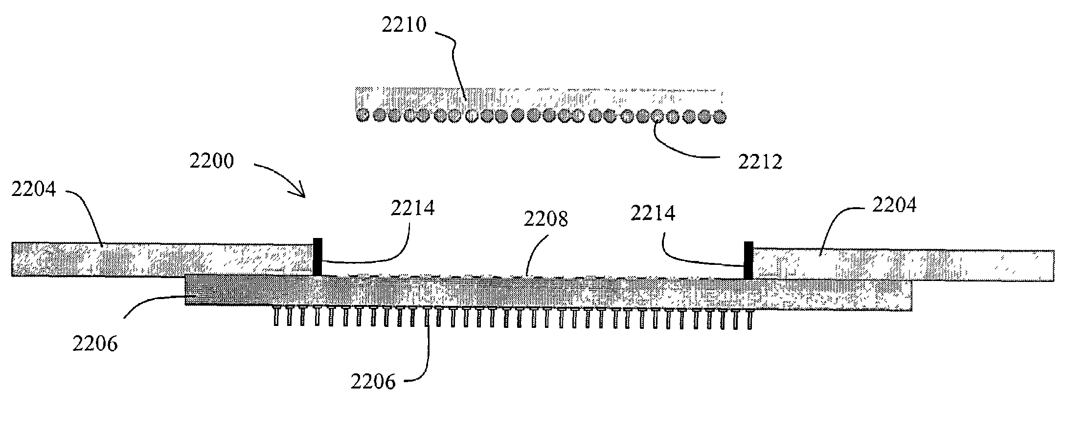
[0041]This embodiment provides a modular package in which the mechanical standoffs serve many purposes. First, they provide a low inductance path directly to the processor, rather than the higher inductance path through the substrate, socket and other elements depicted in FIG. 2. Second, they provide the proper z-axis (typically vertical) physical relationship between the substrate and the circuit board. The modular assembly can be plugged into a socket on the motherboard, and all of the pins on the socket can be used as signal pins instead of power pins. This also allows the processor to be easily separated from the motherboard, even while providing power, if desired.
[0042]This embodiment also provides the advantage of permitting a robust, consistent thermal and mechanical interface to a heatsink or other thermal dissipation device. Compressible or other compliant interfaces can be used to manage the physical and thermal connection between the circuit board, VRM components and other components on the circuit board, as well as the processor. These interfaces can provide a compression thermal coupling for the thermal interface of the microprocessor that can be adapted to a wide range of operating requirements.
[0043]In a second embodiment particularly suited for use with organic land grid array (OLGA) based constructions which may or may not not use interposer boards, the conductive interconnect device comprises concentric conductive spring devices disposed about the periphery of the component. Since this embodiment does

Problems solved by technology

Meeting end user performance requirements with minimal form-factors while increasing reliability and manufacturability presents significant challenges in the areas of power distribution, thermal management, and electromagnetic interference (EMI) containment.
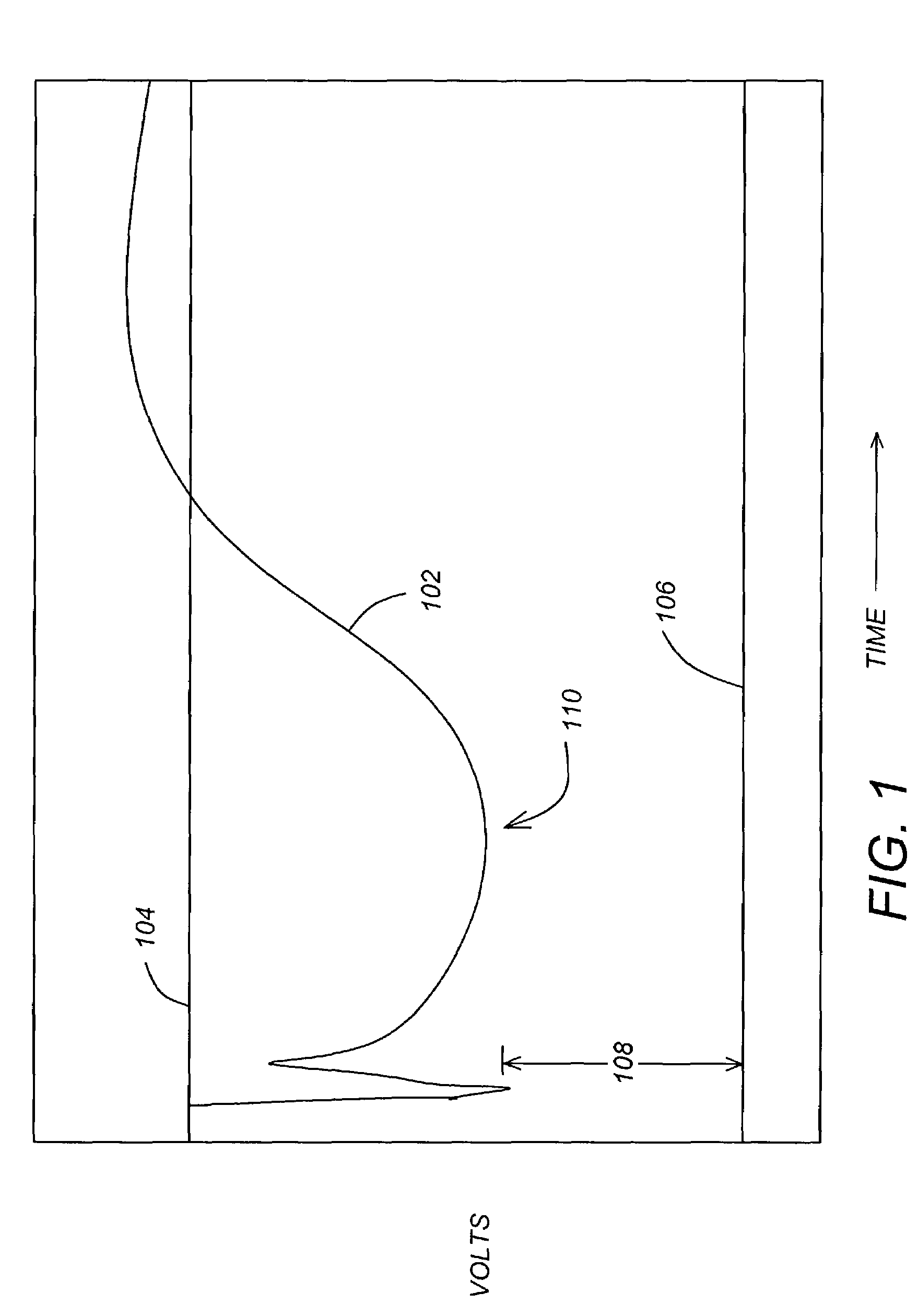
First, the lowered operating voltage of the processor places greater demands on the power regulating circuitry and the conductive paths providing power to the processor. Typically, processors require supply voltage regulation to within 10% of nominal. In order to account for impedance variations in the path from the power supply to the processor itself, this places greater demands on the power regulating circuitry, which must then typically regulate power supply voltages to within 5% of nominal.
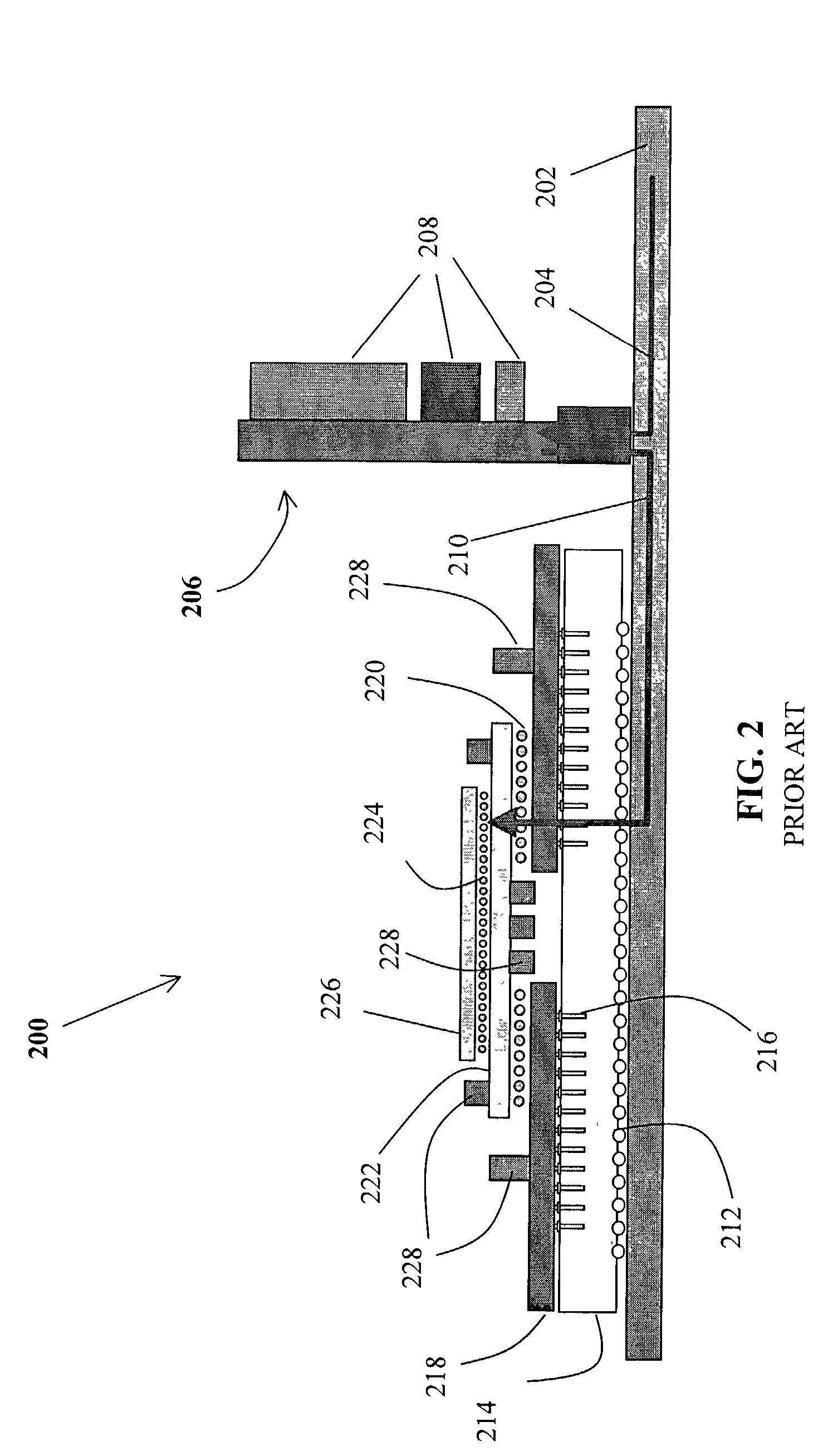
While it is possible to place power conditioning circuitry on the processor package itself, this design is difficult to implement because of the unmanageable physical size of the components in the power conditioning circuitry (e.g. capacitors and inductors), and because the addition of such components can have a deleterious effect on processor reliability.
Such designs also place additional demands on the assembly and testing of the processor packages as well.
Further exacerbating the problem are the transient currents that result from varying demands on the processor itself

Method used


Image

  • Method and apparatus for providing power to a microprocessor with integrated thermal and EMI management
  • Method and apparatus for providing power to a microprocessor with integrated thermal and EMI management
  • Method and apparatus for providing power to a microprocessor with integrated thermal and EMI management

Examples


Example

[0108]FIG. 14 is a diagram presenting a perspective view of a second embodiment of the conductive interconnect device 1400. This second embodiment of the conductive interconnect device is described by two characteristics. First, unlike the previously described embodiment, this embodiment of the conductive interconnect device surrounds the component. Second, unlike the previously described embodiment, this embodiment of the conductive interconnect device establishes electrical connection between the power delivery module 1300 and it's associated circuits and the substrate by use of compressibility in the z (vertical) axis.

[0109]In one embodiment, the conductive standoff device 1400 includes a first conductive standoff portion 1402 and a second conductive standoff portion 1404. In the illustrated embodiment, the first 1402 and second conductive standoff 1404 portions are arranged concentrically. In the illustrated embodiment, the conductive interconnect device 1400 includes a pluralit...


PUM


Abstract

A microprocessor packaging architecture using a modular circuit board assembly that provides power to a microprocessor while also providing for integrated thermal and electromagnetic interference (EMI) is disclosed. The modular circuit board assembly comprises a substrate, having a component mounted thereon, a circuit board, including a circuit for supplying power to the component, and at least one conductive interconnect device disposed between the substrate and the circuit board, the conductive interconnect device configured to electrically couple the circuit to the component.

Description

CROSS-REFERENCE TO RELATED APPLICATIONS[0001]This applications is a continuation of U.S. patent application Ser. No. 09 / 785,892, entitled “METHOD AND APPARATUS FOR PROVIDING POWER TO A MICROPROCESSOR WITH INTEGRATED THERMAL AND EMI MANAGEMENT, by Joseph T. DiBene, II, David H. Hartke, James Hjerpe Kaskade, and Carl E. Hoge, filed Feb. 16, 2001 now U.S. Pat. No. 6,452,113;[0002]which application claims benefit of the following U.S. Provisional Patent Applications which are hereby incorporated by reference herein:[0003]Application Ser. No. 60 / 183,474, entitled “DIRECT ATTACH POWER / THERMAL WITH INCEP TECHNOLOGY,” by Joseph T. DiBene II and David H. Hartke, filed Feb. 18, 2000;[0004]Application Ser. No. 60 / 186,769, entitled “THERMACEP SPRING BEAM”, by Joseph T. DiBene II and David H. Hartke, filed Mar. 3, 2000;[0005]Application Ser. No. 60 / 187,777, entitled “NEXT GENERATION PACKAGING FOR EMI CONTAINMENT, POWER DELIVERY, AND THERMAL DISSIPATION USING INTER-CIRCUIT ENCAPSULATED PACKAGING ...

Claims


Application Information

Patent Timeline
IPC IPC(8): H05K7/06G06F1/18H01L23/427H01L23/433H01R4/64H05K1/02H05K1/14H05K3/30H05K3/36H05K7/10H05K7/20
CPCG06F1/18G06F1/182G06F1/189H01L23/427H01L23/433H01R4/64H05K1/141H05K1/144H05K3/368H05K7/1092H01R12/52H01L2924/15192H01L2924/15312H01L2924/3011H05K1/0206H05K1/0263H05K3/301H05K2201/10318H05K2201/10325H05K2201/10598H05K2201/10704H05K2201/10734H05K2201/2018H05K2201/2036H01L2224/16225H01L2224/32245H01L2224/73253H01L2224/32225H01L2224/73204H01L2224/92125H01L2924/15311H01L2924/00
Inventor DIBENE, II, JOSEPH T.HARTKE, DAVID H.KASKADE, JAMES J. HJERPEHOGE, CARL E.
Owner MOLEX INC
Why Eureka
Try Eureka