Light emitting device

a light emitting device and light technology, applied in the direction of discharge tube luminescent screen, discharge tube/lamp details, luminescent composition, etc., can solve the problems of insatisfactory light emitting device of the prior art, decrease in relative luminance, and difficulty in satisfactorily suppressing the variation of chromaticity of light emitting device, etc., to achieve less variation in color tone, high luminance, and efficient excitation

Inactive Publication Date: 2007-07-24
NICHIA CORP
View PDF44 Cites 23 Cited by
  • Summary
  • Abstract
  • Description
  • Claims
  • Application Information

AI Technical Summary

Benefits of technology

[0018]The first light emitting device according to the present invention having such a constitution as described above can minimize the variability in the emitted light color and improve the unevenness of color tone, since the emission spectrum of the fluorescent substance hardly changes even when the emission spectrum of the fluorescent substance changes due to variability in the manufacturing process.
[0088]Particularly since the second fluorescent substance can be excited also by the light emitted by the first fluorescent substance that is excited by the semiconductor light emitting element, the light emitting device can provide better color rendering performance. It is also made easier to manufacture the light emitting device with better mass productivity. The fourth light emitting device also allows it to extract components of long wavelengths relatively easily while providing high color rendering performance. Moreover, the light emitting device is capable of emitting white light, providing light of a desired intermediate color with high luminance, and allows delicate adjustment of the color tone.

Problems solved by technology

As a result, in the light emitting device of the prior art where two or more kinds of fluorescent substance are used, it has been difficult to satisfactorily suppress the variation of chromaticity of the light emitting device since variability in the emission wavelength of light emitting element affects the chromaticity of the light emitting device.
For the semiconductor light emitting element to be used as light source including illumination by making use of the advantage thereof, the light emitting device of the prior art is not satisfactory and it is required to increase the luminance and improve the mass productivity.
Therefore, there is such a case as the proportion of mixing the red light emitting fluorescent substance must be increased, which results in a decrease in the relative luminance.
When the fluorescent substance is excited by near ultraviolet rays, variability in the wavelength of light emitted by the light emitting element may lead to a decrease in the luminance of red light emitted by the fluorescent substance due to the shift in the wavelength of light that excites the fluorescent substance, thus resulting in a change in chromaticity of light emitted by the light emitting device.

Method used


Image

  • Light emitting device
  • Light emitting device
  • Light emitting device

Examples


embodiment 1

[0107]The light emitting device according to the first embodiment of the present invention is constituted by the combination of:

[0108](1) a semiconductor light emitting element that emits light of a wavelength in ultraviolet region; and

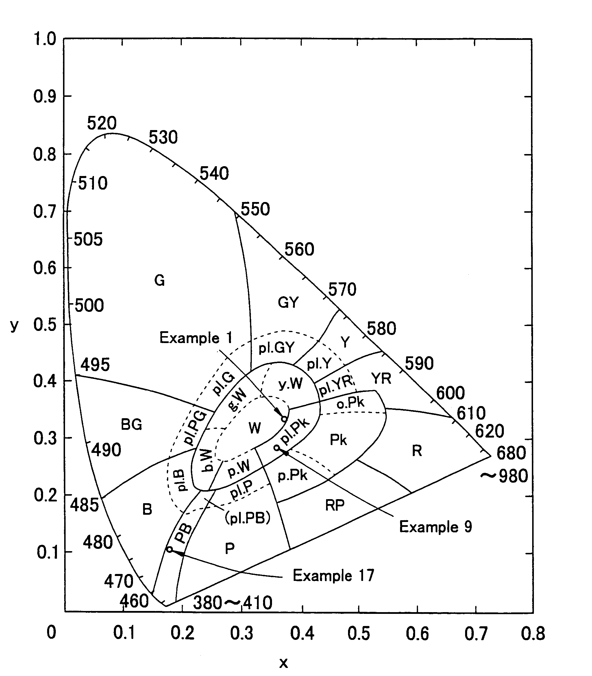
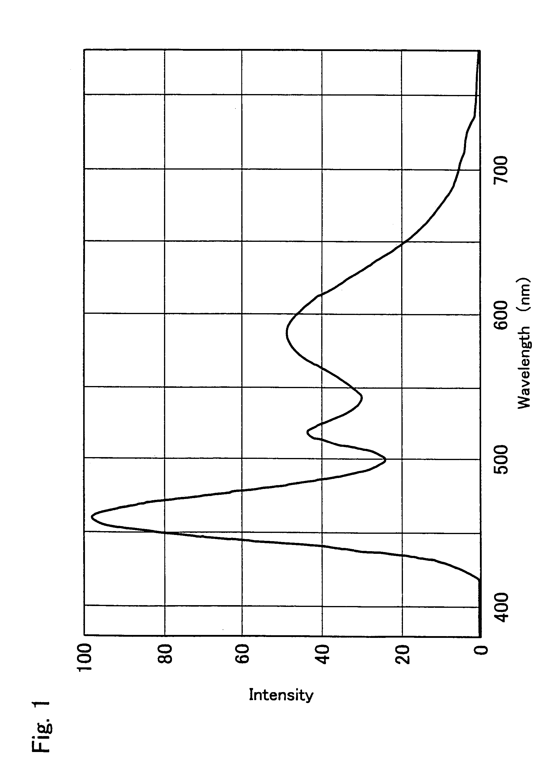
[0109](2) a fluorescent substance including at least one kind of fluorescent substance (first fluorescent substance) that is excited by ultraviolet rays emitted by the light emitting element and has an emission spectrum having two peaks that are complementary colors of each other, so as to provide the light emitted by the fluorescent substance to the outside.

[0110]The light emitting device of the first embodiment having such a constitution as described above is hardly affected by the variability in the emission wavelength of the light emitting element as will be explained later, and the color of the emitted light is determined only by the emission spectrum of the fluorescent substance. Accordingly, such effects can be achieved as less variability in c...

embodiment 2

[0171]The light emitting device according to the second embodiment of the present invention will now be described below.

[0172]The light emitting device of the second embodiment is constituted in the same manner as in the first embodiment, except for using the fluorescent substance that is different from that of the first embodiment.

[0173]The light emitting device of the second embodiment emits light with less color deviation by taking advantage of the fact that the bandwidth of blurred light emitted by the fluorescent substance upon excitation by the light emitting element is less than the bandwidth of blurred light emitted by the light emitting element

[0174]While the semiconductor light emitting element is formed by the MOCVD or other process, some variability occur even among chips that are produced from a same wafer. As a result, a light emitting device that outputs the light emitted by the semiconductor light emitting element tends to produce very large variability. The light em...

example 1

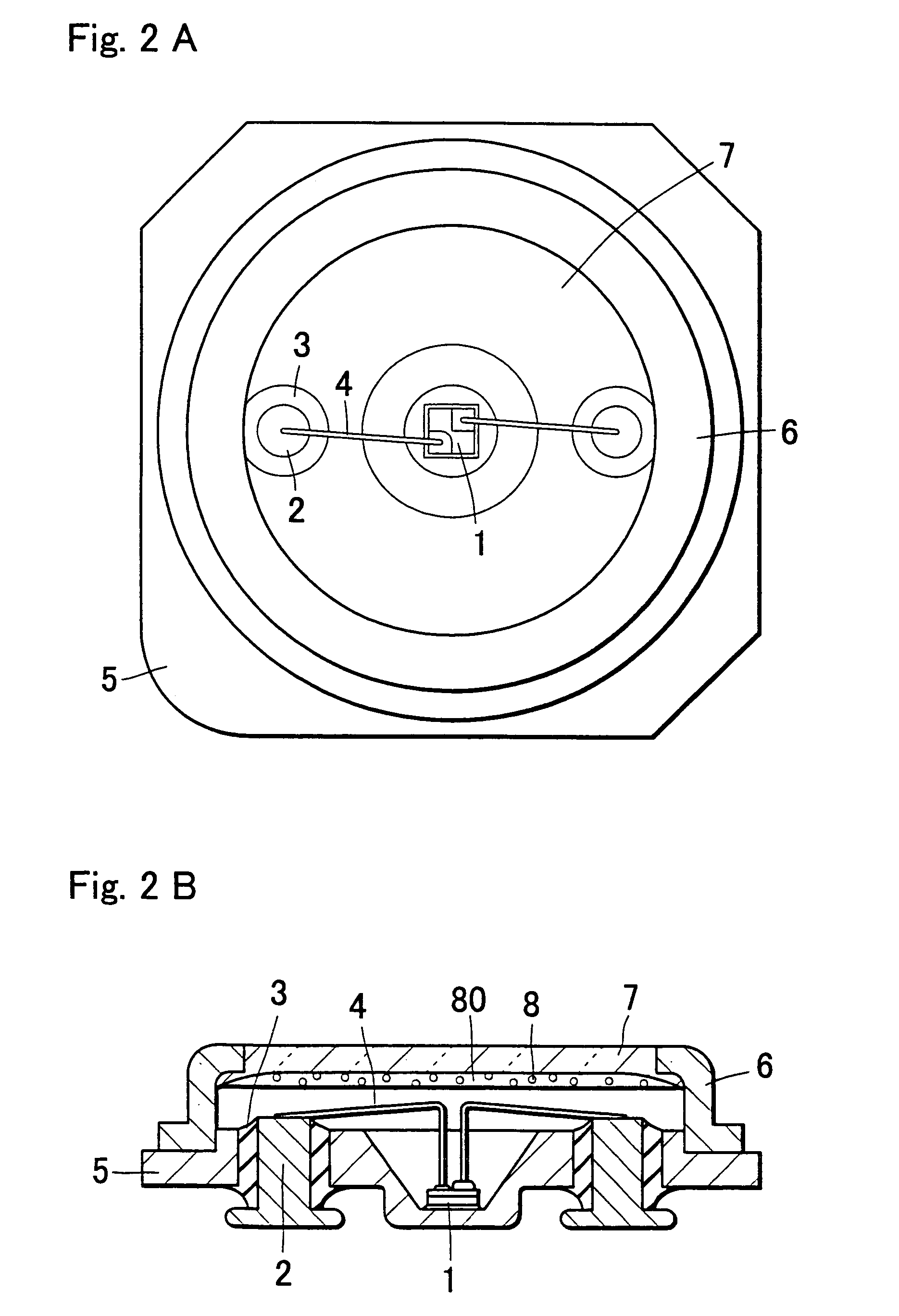
[0268]In Example 1, a surface-mounted light emitting device as shown in FIG. 2 is produced. The LED chip 1 has a light emitting layer that is constituted from a nitride semiconductor made of InAlGaN semiconductor having an emission peak at 375 nm in the ultraviolet region. The LED chip 1 is made by flowing TMG (trimethyl gallium) gas, TMI (trimethyl indium) gas, nitrogen gas and dopant gas together with a carrier gas onto a sapphire substrate that has been washed, so as to form a nitride semiconductor film by MOCVD process. At this time, layers of n-type nitride semiconductor and p-type nitride semiconductor are formed by switching the dopant gas between SiH4 and Cp2Mg.

[0269]The LED chip 1 is made in multiple quantum well structure having such a constitution as five sets of layers are stacked on the sapphire substrate, one set consisting of an n-type GaN layer made of an undoped nitride semiconductor, a GaN layer serving as n-type contact layer for forming an Si-doped n-type electro...


PUM


Abstract

To minimize the variability in the emitted light color and improve the unevenness of color tone, a light emitting device comprises a light emitting element and a fluorescent substance that is excited by the light emitting element, wherein the light emitting element has an emission spectrum in a region from ultraviolet to visible light of short wavelengths, and the fluorescent substance has an emission spectrum that includes two or more emission peaks with at least two peaks of the two or more peaks being in the relation of complementary colors of each other.

Description

CROSS-REFERENCES TO RELATED APPLICATIONS[0001]This application is a divisional of U.S. application Ser. No. 10 / 475,314, filed Oct. 20, 2003 now U.S. Pat. No. 7,091,656, which is the US national phase of international application PCT / JP02 / 03901 filed 19 Apr. 2002, which designated the US. PCT / JP02 / 03901 claims priority to JP Application No. 2001-123457 filed 20 Apr. 2001, JP Application No. 2001-203240 filed 4 Jul. 2001, JP Application No. 2001-288070 filed 21 Sep. 2001 and JP 2001-320201 filed 18 Oct. 2001. The entire contents of these applications are incorporated herein by reference.BACKGROUND OF THE INVENTION[0002]The present invention relates to a light emitting device that uses a light emitting element and a fluorescent substance and can be used for such applications as illumination, display, indicator and other light sources, and particularly to a white light emitting device that uses a fluorescent substance that is excited by the light emitted by a semiconductor light emittin...

Claims


Application Information

Patent Timeline
Patent Type & Authority Patents(United States)
IPC IPC(8): H01J1/62H01L33/06H01L33/32H01L33/38H01L33/40H01L33/50
CPCC09K11/584C09K11/662C09K11/7734C09K11/7739C09K11/7774C09K11/7789H01L33/38H01L33/504H05B33/14H01L33/20H01L33/502H01L2224/48465H01L2224/4903H01L2224/73265H01L2224/45139H01L2924/00011H01L2924/00014H01L2924/00H01L2924/01005H01L2224/45015H01L2924/207
Inventor MURAZAKI, YOSHINORIICHIHARA, TAKASHI
Owner NICHIA CORP
Why Eureka
Try Eureka