System and method for gas analysis using doubly resonant photoacoustic spectroscopy

a photoacoustic spectroscopy and doubly resonant technology, applied in the direction of material analysis using wave/particle radiation, fluid analysis using sonic/ultrasonic/infrasonic waves, etc., can solve the problem of not having an objective measure of when the moisture content has been reduced, and the noise rejection benefits of wavelength modulation may not be realized. problem, to achieve the effect of optimizing the frequency of process tool maintenance, reducing equipment downtime, and speed yield improvemen

Active Publication Date: 2007-09-04
LI COR
View PDF3 Cites 59 Cited by
  • Summary
  • Abstract
  • Description
  • Claims
  • Application Information

AI Technical Summary

Benefits of technology

[0018]The present invention provides a photoacoustic system and method which can use a wide variety of continuous wave (CW) lasers, including inexpensive telecom diode lasers. It provides a small, optically based sensor that is capable of detecting trace contaminants, such as water vapor, at the level of a few ppbv in both inert and corrosive process gases. In-line or at-line monitors according to the present invention will enable wafer fabs to establish correlations between moisture and / or other contaminant gas content and device quality. Precise knowledge of the relationship between contaminant content and device quality will accelerate yield improvement when fabs are introducing new processes. Given the short product lifetime of today's integrated circuits, it is economically vital to bring new circuits to market as soon as possible. When leaks occur in the gas distribution system, moisture monitors in accordance with the present invention will help wafer fab engineers identify the exact location and severity of the leaks sooner and more easily and thereby cut the associated equipment downtime from hours or even days to minutes. In-line or at-line monitors will help engineers identify the root cause of a yield hit sooner, either by revealing a moisture or other contaminant problem or by enabling them to rule out e.g., moisture as the offender. Furthermore, monitors in accordance with the present invention will enable wafer fabs to optimize the frequency of process tool maintenance by using moisture readings to indicate if maintenance is due. By optimizing the frequency of maintenance, wafer fabs will minimize costs associated with test wafers and other consumables. The present invention will also enable wafer fab engineers to measure moisture in process tools after preventive maintenance. After routine preventive maintenance of tools, such as a CVD chamber, engineers normally purge the chamber to remove moisture. However, they typically have no objective measure of when the moisture content has been reduced sufficiently to stop the purge and resume fabrication processes. The monitors of the present invention will enable them to ensure safe moisture levels and to return the tool to productivity as soon as possible.
[0020]A unique aspect of the present invention is that it provides a resonant optical cavity which enhances the optical power used to excite the target analyte contained within a photoacoustic cell. The resonant optical cavity comprises at least two reflecting surfaces. The simplest configuration is a linear cavity with two mirrors (reflecting surfaces). However, the cavity can be composed of any number of mirrors that create a closed path resonant optical cavity. A stable optical cavity can suitably utilize either flat or concave mirrors, or a combination thereof. For simplicity of fabrication, the mirrors will preferably have the same reflectivity and radius of curvature. As an alternative, one of the reflecting surfaces can be a crossed polarizer. At least one optical element in the system will be translatable so as to change the phase of the electromagnetic wave and enable the optical cavity and the modulated laser source to track one another, so that light builds up inside the optical cavity.
[0026]The locking system can either move one of the cavity mirrors, as is typically used in electronic tracking (locking), or move the cavity input mirror as is typically used in optical locking. The most well-known electronic locking technique is Pound Drever Hall [see for example Ye, J, Ma, L S, Hall, J L, J. Opt. Soc. Am. B, 15, 6 (1998) or Spence T G, Harb C C, Paldus B A, Zare R N, Willke B, Byer R L., Rev. Sci. Instrum., 71, 347 (2000)], where the frequency sidebands generate an error signal to feedback to the laser wavelength or cavity length. Other electronic locking methods include [Fox, R W, Oates, C W, Hollberg, L W, “Stabilizing diode lasers to high finesse cavities”, in Cavity-Enhanced Spectroscopies, eds. Van Zee, R D, Looney, J P, Experimental Methods in the Physical Sciences, Vol. 40, Elsevier Science, New York (2002)] a “periodic” locking combined by diode laser current switching, and tracking by dithering the laser current or cavity length [Romanini D, Kachanov A A, Sadeghi N, Stoeckel F, Chem. Phys. Lett., 264, 316 (1997) and Romanini, A. A. Kachanov, and F. Stoeckel, Chem. Phys. Lett., 270, 538 (1997)]. Electronic locking has been demonstrated for both linear and ring optical cavities. Optical locking has been demonstrated using fixed length V-cavities and dithering the position of the input mirror. “Optical” locking of a DFB laser to a single cavity mode produces a strong effect, which narrows the laser emission spectrum (to match the cavity mode linewidth) and significantly enhances both light injection and transmission through the cavity. Detailed descriptions of both the physics and the detailed implementations of this locking scheme have been reported [Morville, J, Chenevier, M, Kachanov, A A, Romanini, D, SPIE Proc., 4485, 236 (2002) and Morville, J, Romanini, D, Chenevier, M, Kachanov, AA, Appl. Opt., 41, 6980 (2002) and Morville, J, Romanini, D, Kachanov, A A, Chenevier, M, Appl. Phys. B, 78, 465 (2004)].

Problems solved by technology

However, they typically have no objective measure of when the moisture content has been reduced sufficiently to stop the purge and resume fabrication processes.
Alternatively, the laser source can be amplitude modulated rather than wavelength modulated, but in this case some of the noise rejection benefits of wavelength modulation may not be realized.

Method used


Image

  • System and method for gas analysis using doubly resonant photoacoustic spectroscopy
  • System and method for gas analysis using doubly resonant photoacoustic spectroscopy
  • System and method for gas analysis using doubly resonant photoacoustic spectroscopy

Examples


Embodiment Construction

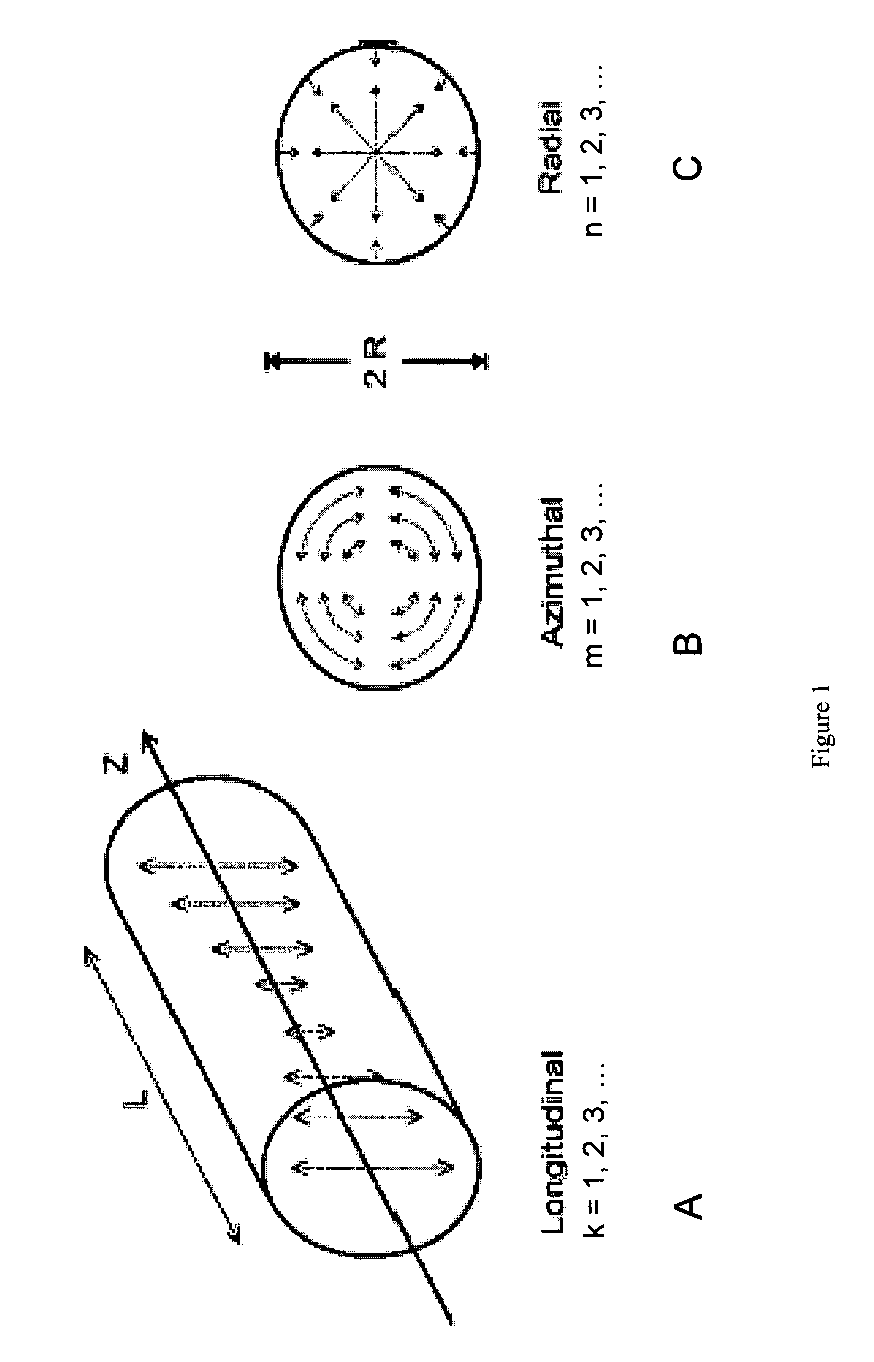
[0043]In understanding the present invention, it is helpful to begin with a brief discussion of the behavior of acoustic waves in a closed volume (i.e., resonator). Insight into this behavior is most commonly obtained by solving equations for the motion of acoustic waves (“acoustic wave equations”) in the resonator geometry under study. The simplest acoustic resonator geometry is a cylinder. A solution of the wave equation in cylindrical coordinates provides the allowed acoustic energy distributions, or modes, that are supported by a given resonator. The solutions are usually given by indices which indicate the “order” of the solution, and are related to the number of times the field Pj goes to zero as a function of the relevant coordinate. The most general solution of the acoustic wave Equation in this geometry is given by Equation 2:

[0044]Pj⁡(r,ϕ,z,t)=pj⁢Cos⁡(m⁢⁢ϕ)⁢Cos⁡(k⁢⁢π⁢⁢zL)⁢Jm⁡(αmn⁢π⁢⁢rR)⁢ⅇ-ⅈ⁢⁢ωt(2)

[0045]In the modal solutions described by Equation 2, the indices k, m, and n...


PUM

PropertyMeasurementUnit
reflectivityaaaaaaaaaa
lengthaaaaaaaaaa
acoustic wavelengthaaaaaaaaaa

Abstract

A method for analyzing gas concentration using doubly resonant photoacoustic spectroscopy, and a doubly resonant photaoacoustic gas detector comprising:i) a continuous wave light beam whose wavelength coincides with an absorption wavelength of a gaseous analyte;ii) a closed path optical cavity having at least two reflective surfaces;iii) an acoustic resonator chamber contained within said optical cavity, and comprising an acoustic sensor for detecting sound waves generated by a gaseous analyte present within said chamber, the light beam passing sequentially into, through and out of said chamber, and being repeatedly reflected back and forth through said chamber, and being modulated at a frequency which is equal to or equal to one-half of an acoustic resonance frequency of said acoustic resonator chamber.

Description

RELATED APPLICATIONS[0001]This application claims the benefit of co-pending, commonly assigned U.S. Provisional Applications Ser. No. 60 / 634,627, filed 9, Dec., 2004 and 60 / 688,595, filed 7 Jun. 2005 the disclosures of which are hereby incorporated in their entirety.FIELD OF THE INVENTION[0002]The present invention relates generally to the field of gas detection and contaminant concentration analysis. In a preferred embodiment, the present invention relates to (but is not limited to) moisture content monitors.BACKGROUND OF THE INVENTION[0003]As semiconductor technology advances and device sizes shrink, the impact of contaminants in the gases used to fabricate these devices becomes increasingly important. Many specialty gases are used in the production of semiconductor devices. For example, a major source of contamination in the chip fabrication process is the presence in process gases of trace amounts e.g., on the order of tens of parts per billion by volume (ppbv) of water. While u...

Claims


Application Information

Patent Timeline
Patent Type & Authority Patents(United States)
IPC IPC(8): G01N21/00
CPCG01N21/1702G01N2021/1704
Inventor SELKER, MARKRIDDLE, ALFREDPALDUS, BARBARA
Owner LI COR
Why Eureka
Try Eureka